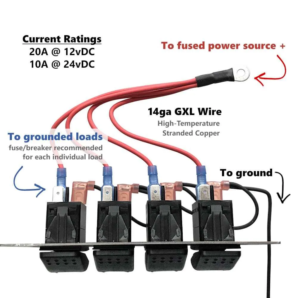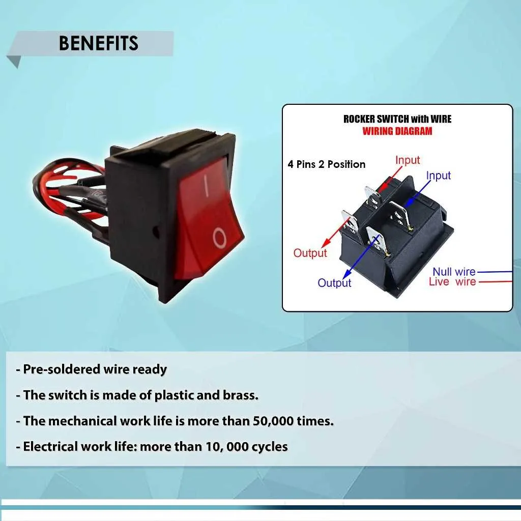
To correctly wire a 4-terminal toggle mechanism, identify the four connections that correspond to two states: on and off. These terminals must be connected in a specific sequence to ensure proper operation. Each of the terminals has a specific role in the circuit, with two providing power, one acting as a ground, and the fourth being the output or control terminal.
Start by connecting the power input terminals to the source voltage, ensuring the polarity matches the device’s requirements. The ground terminal should be connected to the system’s ground or common, while the output terminal will link to the device or circuit you wish to control. Double-check that no terminals are left unconnected to avoid a non-functional setup.
When wiring, consider the expected current load and voltage specifications to prevent overheating or electrical faults. Use appropriate gauge wires and connectors based on the power rating of the circuit to avoid issues with heat dissipation and safety hazards. Secure all connections with reliable insulation or terminal blocks to prevent accidental shorts.
By following these specific instructions, you ensure a stable and functional connection, reducing the risk of malfunctions or damage to components. Always verify the connections with a multimeter before finalizing the installation to ensure everything is correctly set up.
Electrical Connection Guide for 4-Terminal Toggle Mechanism
For optimal performance, ensure the terminals are properly aligned before making any connections. The first two terminals are typically used for controlling power flow to the device, while the remaining two terminals are for controlling additional features, such as light indicators or secondary circuits.
Power Control Setup: Connect the primary power source to the first terminal, and link the second terminal to the device you want to control. This setup allows you to toggle the device on and off. Ensure that the wire gauge matches the required current rating for safety.
Secondary Features: Use the third and fourth terminals to control auxiliary features, such as indicator lights. If you’re wiring an indicator, connect the third terminal to the positive side of the light, and the fourth terminal to the negative side. This provides visual confirmation when the device is activated.
Tip: Double-check the orientation of the mechanism to avoid reverse polarity, especially if you’re working with lights or other sensitive components. Always confirm the device’s voltage rating before completing the setup to prevent damage.
Understanding the Configuration and Functionality
When connecting a four-terminal device, it is crucial to correctly identify the roles of each terminal to ensure proper operation. Typically, you will find two pairs of terminals: one for power input and the other for power output. These terminals are designed to handle specific tasks depending on the device’s intended use.
Terminals for Power Input are often marked to accept the supply voltage. These should be connected to the main power source, ensuring proper polarity. If the device operates at a certain voltage, ensure the correct terminal receives the positive lead, and the negative lead is connected to the appropriate terminal for ground.
Output Terminals allow the controlled power to flow through to the load. Depending on the activation state, either one or both output terminals will be active. In the “off” state, the output is disconnected, preventing the current from reaching the connected device. Once activated, power is transmitted from the input terminals through to the load via the output terminals.
Neutral terminals often serve as a return path, ensuring that current completes the circuit back to its source. When connecting, be sure that these return paths are securely linked to the ground or neutral section of your electrical setup.
For a reliable connection, confirm that each terminal is securely fastened and that the conductors used can handle the intended load. Any loose connections can result in unreliable operation or even damage to the system.
Step-by-Step Guide to Wiring a 4 Pin Rocker Switch

Follow these steps carefully to connect your 4-terminal control unit for optimal functionality.
- Identify the terminals: The first step is to locate the four terminals on the device. Typically, they consist of two for input and two for output, depending on the design. Ensure each terminal is correctly labeled, often as “Common,” “Normally Open,” “Normally Closed,” and “Power Input.”
- Prepare your power source: Connect the input terminal to your power supply. This will be your live or hot wire, usually marked as “+” or “L.” Double-check the voltage specifications of your unit to avoid any damage.
- Connect the output terminals: One of the output terminals will be for positive output, while the other will be negative or ground. These terminals are typically labeled “NO” (Normally Open) and “NC” (Normally Closed). If you need the device to be active when the control is turned on, connect the positive output to the “NO” terminal and the ground to “NC.”
- Test the circuit: Before finalizing the installation, temporarily power up the system and check for continuity across the terminals. This ensures proper electrical flow when the control is toggled.
- Mount the component: Once the wiring is confirmed, mount the device in place, ensuring there is no strain on the connections. Use appropriate mounting hardware to secure it tightly to the desired location.
- Secure connections: Finally, use electrical tape or other suitable insulators to prevent accidental shorts. Ensure all exposed wire ends are properly covered and secured for safety.
By following these detailed steps, you ensure the device functions correctly and safely within your setup. Always remember to verify voltage ratings and avoid overloading to prevent damage.
Troubleshooting Common Wiring Issues with 4 Pin Rocker Switches
Verify connections first. Loose or improperly connected wires are the leading cause of malfunctions. Make sure all terminals are securely connected and free from corrosion or rust. Clean and tighten any loose connections as necessary.
If the device does not turn on or off, check the power supply. Ensure the voltage rating matches the required specification for your setup. A power surge or incorrect voltage could prevent the mechanism from functioning.
Test for a blown fuse if the unit remains unresponsive. Fuses protect against overcurrent and can often blow when there’s a short or overload. Replacing the fuse can resolve power issues.
Inspect for a short circuit. A short can occur when wires touch each other or the wrong terminals are connected, leading to a complete malfunction. Look for damaged insulation or exposed copper that might cause this issue.
If only one terminal is not working, check for incorrect placement of wires. Ensure that each wire is going to the correct location based on the device’s design. Refer to the product manual if needed.
Test continuity with a multimeter to ensure that electrical current is properly flowing through the setup. A lack of continuity often points to a broken connection or faulty component.
Lastly, if everything seems correct but issues persist, try replacing the component entirely. Internal damage to the mechanism or worn-out contacts may be the root cause that basic troubleshooting can’t resolve.