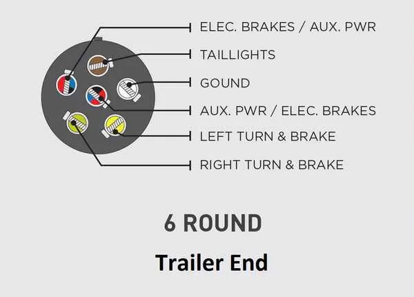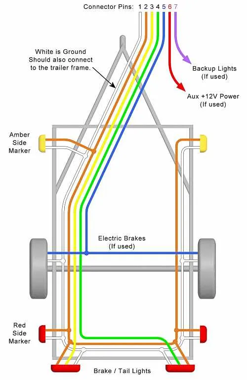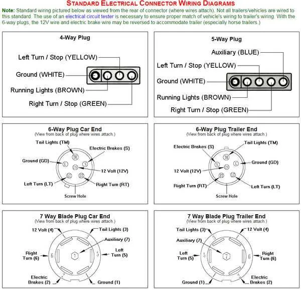
For optimal trailer hook-ups, it’s crucial to understand the wiring setup for a 6-pin connection. A clear layout ensures each component functions correctly, from brake lights to turn signals. The first step is identifying the necessary color coding and pin configuration to avoid any miswiring, which can lead to malfunctioning lights or poor trailer control.
Start by connecting the ground wire to the designated pin to ensure proper electrical flow. Then, proceed with the left turn signal and right turn signal wires, ensuring each is linked to the correct terminal for effective signaling during towing. Pay close attention to the brake light wire, which should be linked to its own dedicated pin for proper brake signal operation.
It is also vital to incorporate a reverse light wire for safe maneuvering when the towing vehicle is in reverse gear. Finally, the auxiliary power wire should be connected to the final pin to support additional power needs, such as those required by electric brakes or other trailer accessories. Always check each connection thoroughly for secure attachment before use to ensure smooth and safe towing.
Wiring Setup for a 6-Pin Connector

For a proper electrical connection between your vehicle and attached load, follow these steps for a 6-pin connection system:
- Pin 1: Ground – Connect the ground wire (usually white) to this pin to establish a common ground between the vehicle and cargo.
- Pin 2: Left turn signal – Attach the wire (typically yellow) from your vehicle’s left turn signal to this pin.
- Pin 3: Right turn signal – The wire (usually green) from the right turn signal on your vehicle should be connected here.
- Pin 4: Brake lights – The red wire from the brake light system should be routed to this pin to activate brake lights when needed.
- Pin 5: Taillights – A wire (often brown) for standard taillight illumination should be linked to this pin for nighttime visibility.
- Pin 6: Reverse lights – Use a white wire to connect the reverse lights of your vehicle to this pin, ensuring proper visibility when reversing.
Ensure that each wire is securely connected and protected from potential damage by using appropriate weatherproof connectors. Double-check for proper function after installation, confirming that each light operates as expected before use.
Correct installation of these connections will ensure reliable signaling and lighting performance, improving safety when towing or hauling a load.
How to Wire a 6-Pin Connector for Towing

Start by ensuring the appropriate gauge of wire for each function. Use 12-gauge wire for the main power circuit, 14-gauge for the brake signal, and 16-gauge for auxiliary functions. Strip the wire ends about 1 inch to make solid connections. Secure the wire terminals to the pins in the plug by crimping or soldering as needed for a reliable, long-lasting connection.
Pin Functions: Connect the main power line (usually brown) to the pin providing 12V power for lighting. The white wire typically serves as ground, attaching to the chassis. The yellow or green wire goes to the brake light circuit, while the blue wire is for auxiliary brakes if applicable. If needed, use the remaining pins for reverse lights or additional functions, according to your specific needs.
Securing Connections: Ensure each wire is firmly attached and insulated to avoid shorts. Use electrical tape or heat shrink tubing to cover exposed sections of the wire after securing them to their respective terminals. Regularly check for wear and corrosion, as these connections are exposed to harsh environments.
Final Testing: After all connections are made, test the setup with a multimeter to verify each function operates correctly. Check brake lights, turn signals, and any other electrical components. If the system doesn’t work properly, inspect the ground connection or the wire connections for potential faults.
Common Issues in 6-Pin Connector Systems and How to Troubleshoot
Faulty ground connection is one of the most frequent causes of electrical malfunctions. Ensure the ground wire is securely attached to a clean, corrosion-free metal surface. A weak or inconsistent ground can cause flickering lights or non-functional circuits.
Blown fuses often occur when there’s a short circuit or power overload. Inspect all fuses related to the system and replace any that appear damaged or burned out. Always use fuses rated for the correct amperage to prevent further issues.
Corroded connectors can lead to poor signal transmission, causing partial or complete loss of power. Clean the pins of the connectors using a wire brush or contact cleaner to remove any corrosion, and apply dielectric grease to prevent future buildup.
Miswired connections can result in reversed functions or no power at all. Double-check the pin configuration against the manufacturer’s guidelines. Ensure each wire is connected to its corresponding terminal, as mistakes here can cause shorts or failure to operate lights and brakes correctly.
Damaged or frayed wires are common, especially in systems exposed to the elements. Inspect the entire cable length for any visible signs of wear or cuts. Replace any sections showing significant damage to prevent further power loss or potential safety hazards.
Interference from other electrical components can disrupt the system’s performance. If you’re experiencing flickering lights or inconsistent behavior, consider isolating the affected components and testing the system with minimal load to identify sources of interference.
Upgrading Your Vehicle’s Electrical System to Support a 6-Pin Connector
To enable your vehicle to handle a 6-pin connector, start by ensuring the power supply is equipped to manage the additional circuits. Begin by installing a dedicated 12V power line from your vehicle’s battery to the connector. This will support the auxiliary power needs of connected devices.
Next, verify that your vehicle’s existing connectors are compatible with the added functions. You will need to integrate the brake light, reverse light, and auxiliary circuits into the system. For the brake light, connect a 20A fused wire from the brake switch to the connector, ensuring that it’s properly routed to avoid interference with other vehicle functions.
When connecting reverse lights, use a separate circuit from the main lighting system to prevent overloading. Typically, a 14 AWG wire is sufficient for these connections. Ensure proper grounding for all components to prevent any issues with signal transmission.
After completing the wiring connections, test all circuits for correct operation. Verify the brake, reverse, and auxiliary lights, as well as the power output, ensuring everything is functioning properly before final installation.