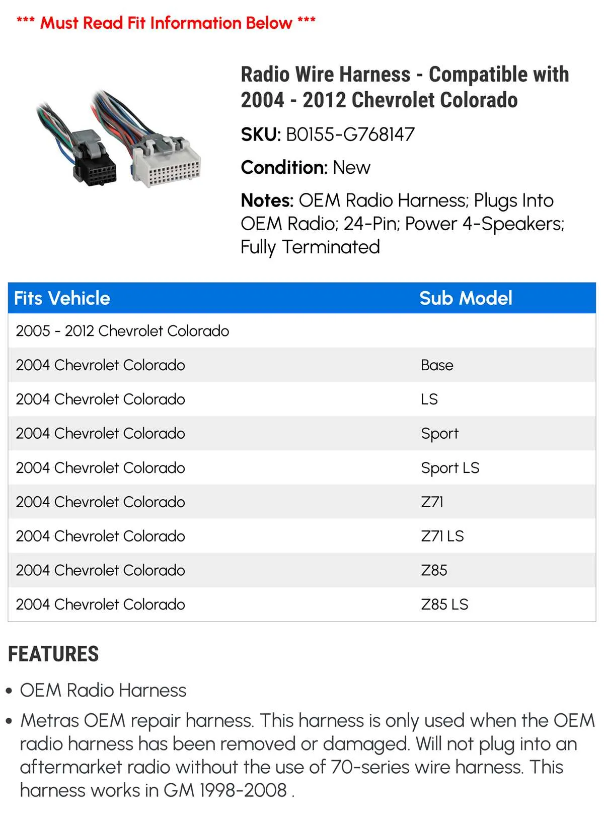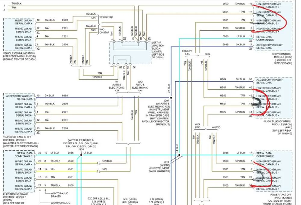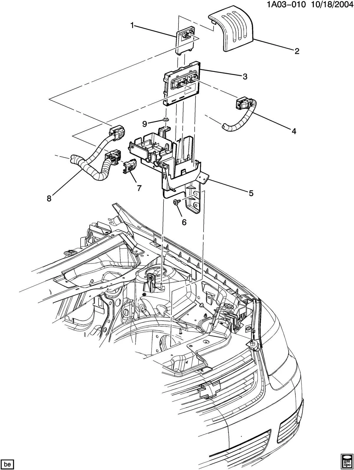
To ensure optimal functioning of the electrical system, it’s essential to have a clear understanding of the connector configurations. These diagrams provide detailed illustrations of how the various components are wired and interconnected, helping to avoid costly mistakes during repairs or modifications.
First and foremost, always refer to the specific schematic tailored to your vehicle’s model year and trim. Even minor differences between similar models can lead to discrepancies in the electrical connections, affecting system performance.
For accurate troubleshooting or upgrading, focus on the essential components, such as the battery terminals, engine connections, and key control circuits. Familiarize yourself with color-coding systems used in these schematics to quickly identify wires and their corresponding roles in the system.
Using these layouts effectively can save time and reduce the risk of damaging sensitive parts. Ensure you have the necessary tools for safe disconnection and reconnection of wires, and always double-check the continuity of each circuit after completing any work.
Electrical System Connection Overview
To ensure proper functionality, refer to the wiring connection schematic specific to your vehicle model. Pay attention to the color-coded wires and terminal placements as they correspond to the various components. For a thorough understanding, each wire’s route should be traced from the fuse box to the associated parts, such as the engine control unit, sensors, and lighting systems.
Start by identifying the main power feed that connects to the battery, and follow the smaller gauge wires for signals going to the ignition switch, relays, and other accessories. The ground connections are crucial for preventing electrical faults, so ensure all grounding points are clean and secure. For connectors, check if they are correctly seated and not showing any signs of corrosion or wear.
In cases of malfunction, a detailed inspection of each wire segment is necessary. Use a multimeter to test for continuity and voltage drop. If you suspect a short, identify the exact section of the circuit by systematically checking each segment against the reference chart. It’s essential to replace any damaged cables with the same specifications to maintain the system’s integrity.
How to Read the Electrical Circuit Layout for Troubleshooting

Start by identifying the main sections of the schematic, such as power distribution, ground connections, and signal paths. This will help you locate specific components that may be malfunctioning.
- Examine the color codes for each wire. These represent different circuits and are vital for correctly interpreting the connections.
- Understand the pinouts for connectors. They indicate which wires correspond to specific terminals, ensuring proper connectivity when repairing or replacing parts.
- Pay attention to wire gauges. Thicker wires handle higher current loads, while thinner ones are used for low-power applications.
Use the chart to trace power flow through the system. By following the pathway from the power source to the component, you can identify where the voltage might be dropping or where a short could exist.
- Verify continuity in each wire segment using a multimeter. If you detect no continuity, it points to a break in the circuit.
- Check for grounding issues. Poor grounding can lead to erratic electrical behavior and component failure.
If troubleshooting specific components, refer to the legend provided. It will match the symbols with their corresponding parts and functions, ensuring correct interpretation of the layout.
- Focus on fuses and relays. These often protect the system from overloads and can be a source of problems if damaged.
- For connectors, ensure that the wire colors and positions match exactly. Misconnections can cause system failure.
Test connections at various points using a voltage tester or oscilloscope. This ensures the signals are as expected at the correct intervals in the circuit.
Finally, make sure to follow the suggested routing paths for wires during repairs. Incorrect positioning can lead to short circuits or signal interference.
Step-by-Step Guide to Identifying and Fixing Electrical Issues in Your Pickup
Start by inspecting all visible connections and components for any signs of corrosion, wear, or damage. Focus on the main cables running from the battery and ensure the connections are clean and tight. Use a multimeter to check for continuity across connectors, especially in high-wear areas like the engine compartment and under the dashboard.
Next, isolate any faulty sections by carefully checking the flow of power through each circuit. If a particular feature, such as lights or windows, fails, inspect the associated fuses and relays. Replace any blown fuses and check if the issue persists.
If power loss or irregular behavior is observed in certain accessories, remove the protective sheathing on the wires in that specific area. Look for exposed wires, breaks, or shorts. Sometimes, wires may rub against nearby metal surfaces, causing intermittent issues that are hard to diagnose without proper inspection.
For a more thorough check, use a wiring diagram tool to trace the electrical path and identify any areas where voltage drops unexpectedly. Pay attention to connectors that are prone to loose or poor connections, and always clean contact points before reassembly.
To repair damaged cables, use the appropriate gauge of wire and crimp connectors. Ensure all connections are insulated and protected from moisture. When fixing any broken sections, make sure to route the new wire in the same manner as the original to avoid future damage.
After fixing, test the functionality of all systems, including the lights, windows, and interior electronics. Perform a final check for continuity and ensure no further issues remain. If necessary, use electrical tape or protective sleeves to keep the wires safe from heat and friction over time.
Common Electrical Issues and Troubleshooting Tips

When encountering electrical malfunctions, start by checking the connectors for signs of corrosion or loose connections. Corroded pins can cause intermittent power loss, leading to faulty signals or components not receiving adequate power.
Next, inspect the insulation for wear or cuts. Over time, exposed wires can short circuit, causing fuses to blow or components to malfunction. If the insulation appears damaged, it’s crucial to replace the affected section before further damage occurs.
Another frequent issue is poor grounding. A weak or disconnected ground can disrupt the entire system, resulting in erratic behavior of lights, sensors, or other electronics. Ensure that all ground connections are clean, secure, and free from rust or dirt.
If your electrical components are inconsistent, it could be a sign of voltage drop. This can occur due to damaged wires or poor contact points. Measure voltage at various points and compare readings to manufacturer specifications to locate any areas of resistance.
Pay close attention to the condition of the fuse box. Corrosion or burn marks around the fuses could indicate that the system has been overloaded. Replacing a fuse is easy, but persistent overloads often require further inspection of the power delivery system.
Lastly, faulty sensors or modules can often be traced back to issues with signal transmission. If you’re experiencing sensor-related problems, check the associated wiring for loose or damaged connectors. Replacing a faulty sensor might resolve the issue, but always verify the integrity of the wiring before proceeding.