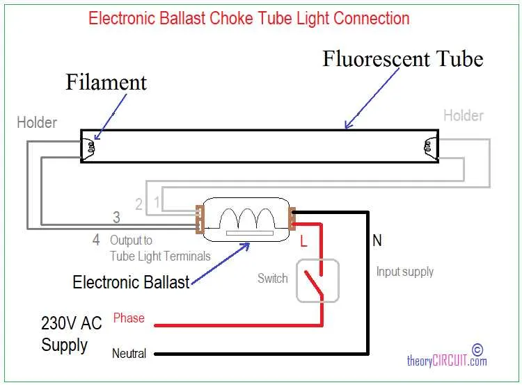
To ensure proper functionality and safety, connect the power input leads to the designated terminals marked for line and neutral. Verify that the voltage rating matches the specifications indicated for the device supporting four fluorescent tubes. Use insulated connectors rated for the expected current to prevent overheating and maintain a secure connection.
Follow the sequence: link each starter output to the corresponding fluorescent fixture, observing polarity and wire color codes commonly used in commercial lighting setups. Parallel wiring of the filaments should be avoided to prevent uneven current distribution and premature failure of the components.
Grounding is critical – attach the grounding conductor to the metal chassis or dedicated ground terminal to minimize electrical hazards. Double-check that no loose strands or exposed copper are present before energizing the system.
4 Fixture Power Supply Connection Guide
For a four-light fixture electronic transformer setup, connect the input leads to a 120V or 277V power source according to specifications. The common line (usually black) should be attached to the live feed, while the white lead connects to neutral. The green or bare conductor must be grounded properly to ensure safety and compliance with electrical codes.
Output leads are divided into pairs, each pair powering two fluorescent tubes. Typically, two pairs of colored wires (often red and blue) run from the device to the sockets. Ensure that each pair corresponds to the correct terminals on the bulb holders, matching polarity and fixture requirements.
Use wire nuts or push-in connectors rated for the specific amperage to secure all connections firmly. Avoid mixing leads from different pairs to prevent short circuits or uneven current distribution. Verify all conductors for damage or wear before installation.
When mounting the control unit inside the lighting enclosure, allow adequate ventilation to prevent overheating. Follow manufacturer instructions on maximum fixture load and maintain clearances around the components.
Step-by-Step Connection of a 4-Lamp Fluorescent Power Supply
Begin by ensuring the power source is turned off before handling any electrical components. Identify the input leads on the device–typically, these include the live (black), neutral (white), and ground (green or bare copper) conductors. Connect the live wire to the input terminal marked “L” and the neutral wire to the terminal marked “N”. Secure the grounding wire to the designated grounding point.
Next, locate the output wires, which are generally grouped in pairs for each light fixture. For a quartet setup, there will be eight output conductors, often color-coded. Match each pair of wires to the corresponding fluorescent tube ends as indicated by the manufacturer’s color key. Usually, pairs such as red and blue or yellow and white are used for individual fixture connections.
Make sure all wire connections are firmly twisted and insulated with wire nuts or electrical tape to prevent shorts. Route the cables neatly to avoid tension or interference with moving parts. After completing all connections, double-check continuity with a multimeter to confirm proper contact and no unintended shorts.
Finally, restore power and observe the fixtures for consistent ignition and steady illumination. If flickering or failure occurs, re-inspect connections and verify that the wiring colors correspond exactly to each fixture’s pin configuration. Properly connected units will function efficiently and extend the operational lifespan of the setup.
Troubleshooting Common Electrical Issues in 4-Unit Light Fixtures

If you’re experiencing problems with your 4-light configuration, follow these steps to identify and correct common electrical faults.
- Check the Power Source: Ensure that the power supply is working correctly and consistently. Test the outlet or circuit breaker to confirm the current is being supplied.
- Examine the Connections: Loose or improperly secured connections are the most frequent cause of electrical faults. Inspect all terminal connections and ensure they are firmly tightened.
- Verify Component Functionality: If one or more units are not operating, test each individually to rule out failure. Replace any malfunctioning parts and recheck the setup.
For more complex issues, follow this step-by-step guide:
- Test for Continuity: Use a multimeter to check for continuity in all electrical paths. Lack of continuity indicates a break in the circuit.
- Inspect for Overheating: Excessive heat may point to overloading or faulty components. If a specific part is hot to the touch, it likely requires replacement.
- Correct Wiring Order: Double-check the sequence of electrical components. Incorrect sequencing can prevent the system from working efficiently or at all.
Addressing these points can resolve many of the issues seen in setups with multiple lighting elements. If the problems persist, it might be necessary to consult with a qualified electrician for more in-depth diagnosis and repair.
Choosing Correct Wire Gauge and Color Coding

Use 14 AWG or 12 AWG wire for optimal current capacity, depending on the total load and installation environment. For most standard applications, 14 AWG is sufficient, but if higher amperage is required, such as in industrial settings, 12 AWG is recommended.
For clear identification, follow the industry-standard color codes. Typically, black is used for the hot wire, white for neutral, and green or bare wire for ground. Ensure that the wires are properly marked for easy identification during maintenance or troubleshooting.
Avoid using wires with insufficient insulation. Ensure the wire insulation rating matches or exceeds the expected voltage to prevent overheating or potential failure. Use heat-resistant wire types for areas with high temperatures or constant load.
For each connection, ensure that wires are firmly twisted or securely connected using appropriate connectors to minimize risk of loose connections. Tighten connections properly to avoid electrical arcing or fire hazards.