Begin by verifying fuse assignment in the rear fuse box located behind the left luggage compartment trim. Use a multimeter to check continuity across fuses F32/5 (15A) and F32/9 (7.5A), which typically support the exterior lighting logic and communication interface.
Connector X30/7 should be your next focus. This 46-pin plug distributes power and control signals to multiple systems including tailgate electronics, parking sensors, and trailer module. Pay close attention to pin 13 (CAN-L) and pin 14 (CAN-H) for network integrity; these lines must show 60 ohms resistance when terminated correctly.
When tracing signal flow, refer to the ground points W35/4 and W35/5 near the left wheel arch. Poor grounding here can result in intermittent issues such as malfunctioning rear lights or backup camera errors. Use a chassis ground reference to test for voltage drop under load.
Wire colors to watch: brown (ground), red/blue (12V ignition-controlled), and green/yellow (data bus). Use heat-shrink crimp connectors for repair to ensure moisture resistance and long-term reliability in the trunk environment.
To isolate faults, disconnect the unit and individually test pins for voltage using the key-on engine-off state. Be cautious not to send voltage back into the bus line; use back-probing techniques through the connector instead of piercing insulation.
Connector Pinout and Signal Allocation Overview
Begin with verifying the harness linked to the rear fuse distribution node located in the trunk’s right-side compartment. Check plug X30/7 for correct pin allocation: pin 1 (power supply from front fuse box via circuit 30), pin 2 (ground), pin 3 (CAN-L), and pin 4 (CAN-H).
For lighting circuits, connector X30/6 manages tail lamps: left tail light feed is typically assigned to pin 7 (output to outer lamp cluster), while pin 9 serves the inner brake/indicator. Ensure continuity and voltage output match expected values during active operation.
The signal from the parking aid ECU routes through connector X30/8, pins 5 and 6, carrying control signals for ultrasonic sensors. When reverse gear is engaged, monitor for a 12V pulse through pin 5.
Heated rear window and wiper motor relays are controlled via output lines from the central control processor, often interfacing through X30/5. Confirm relay coil activation voltage reaches 12V across pins 2 and 6 when defrost or rear wiping is engaged.
Power consumption management integrates LIN-bus communication on X30/9. Pin 3 carries the LIN signal line; ensure correct signal voltage swings between 0V and 12V during command transmission.
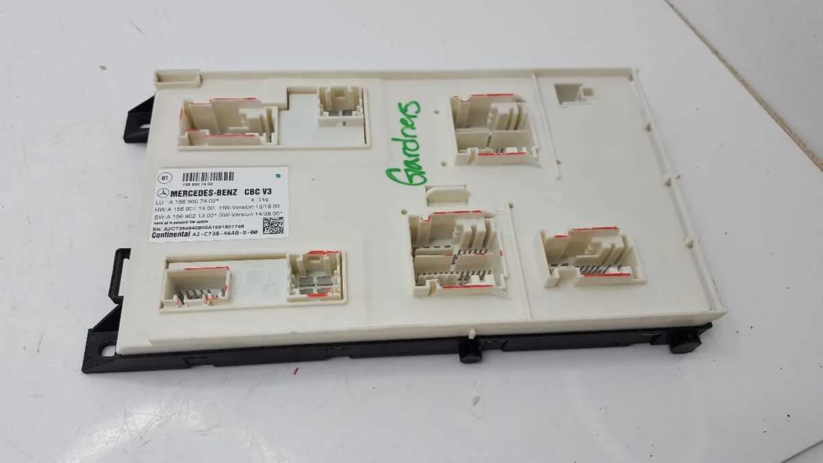
Pin Configuration and Connector Layout of the Rear SAM Module

Always verify the orientation of each socket before applying power. Misalignment can result in short circuits or erroneous sensor feedback.
The primary connector labeled Connector A typically contains 32 terminals. Key assignments include:
- Pin 1: Left tail lamp feed (12V, fused output)
- Pin 7: Ground return for parking sensors
- Pin 13: CAN-L communication line
- Pin 14: CAN-H communication line
- Pin 28: Reverse light trigger
Connector B supports power distribution and is equipped with 18 terminals:
- Pin 2: Right fog lamp signal
- Pin 6: Power supply for auxiliary trailer socket
- Pin 11: License plate light
- Pin 17: Output to tailgate control unit
Each connector housing is color-coded: black for power functions, gray for signal lines, and green for diagnostics. Ensure all terminals are seated with a resistance value below 0.3 ohms for reliable connectivity. Use a digital multimeter in continuity mode to verify grounding paths.
Use dielectric grease on all contact surfaces during reassembly to prevent oxidation and moisture ingress. Secure all locking tabs to avoid vibration-related disconnections.
Wiring Paths for Rear Lighting, Sensors, and Power Distribution
Route all tail lamp conductors through the left-side trunk channel, maintaining separation between high-current and signal lines to minimize interference. Utilize the dedicated ground point G900 near the left wheel arch for all illumination circuits to ensure consistent grounding.
Reverse sensor leads must be shielded and directed via the central floor tunnel harness. Splice connections for the PDC controller should be performed at node X30/8 to maintain CAN bus integrity. Avoid routing proximity sensor lines adjacent to power feed lines; maintain at least 50 mm distance to prevent signal degradation.
Distribute voltage for power sockets and rear wiper motor from the central junction unit located beneath the luggage compartment trim. Fuse allocation F31 and F34 should be used for accessories and motor drives, respectively. Maintain separate return paths to the chassis ground to isolate motor-induced voltage spikes.
Use twisted-pair construction for signal communication between the radar control unit and the central processor, ensuring EMI shielding. All control conductors must terminate in connector block N10-2, pin assignments as per the electrical layout chart, verifying continuity before reassembly.
Troubleshooting Common Signal and Ground Issues in Rear SAM Circuits
Start by verifying ground continuity at pin 31 of connector A3/2 using a multimeter set to resistance mode. Ensure the reading is below 0.5 ohms to chassis ground.
- Check for voltage drop across the ground wire during load; if it exceeds 0.2V, inspect the crimp and chassis bonding point near the left rear wheel arch.
- For intermittent signal failures, probe pin 7 of connector A3/1 while operating tail lamps. Confirm 12V with the light on and 0V with it off.
- Use an oscilloscope to examine LIN bus activity at pin 11 of connector A3/3; a flat line or irregular waveform indicates a fault in the associated control unit or a shorted wire.
- Inspect the GND splice pack S301, typically located under the left cargo floor trim. Corrosion here can introduce floating ground conditions, leading to random signal errors.
- Measure signal integrity on CAN Low (pin 5) and CAN High (pin 6) of connector A3/4. Expect a 2.5V idle level with 1V differential during communication.
When diagnosing a non-responsive output, such as the license plate lamp, confirm signal presence at pin 3 of connector A3/2. If 12V is absent, backtrace the control logic from the junction box to the interior fuse relay module, checking fuse F13 (15A) and the relay output.
- Disconnect the relevant tail harness connector and check for continuity between output pin and the lamp socket.
- Check for insulation damage near trunk hinge area; flexing can cause hidden breaks.
- Use a load tester instead of a standard test light to simulate actual current draw; some faults only appear under load conditions.