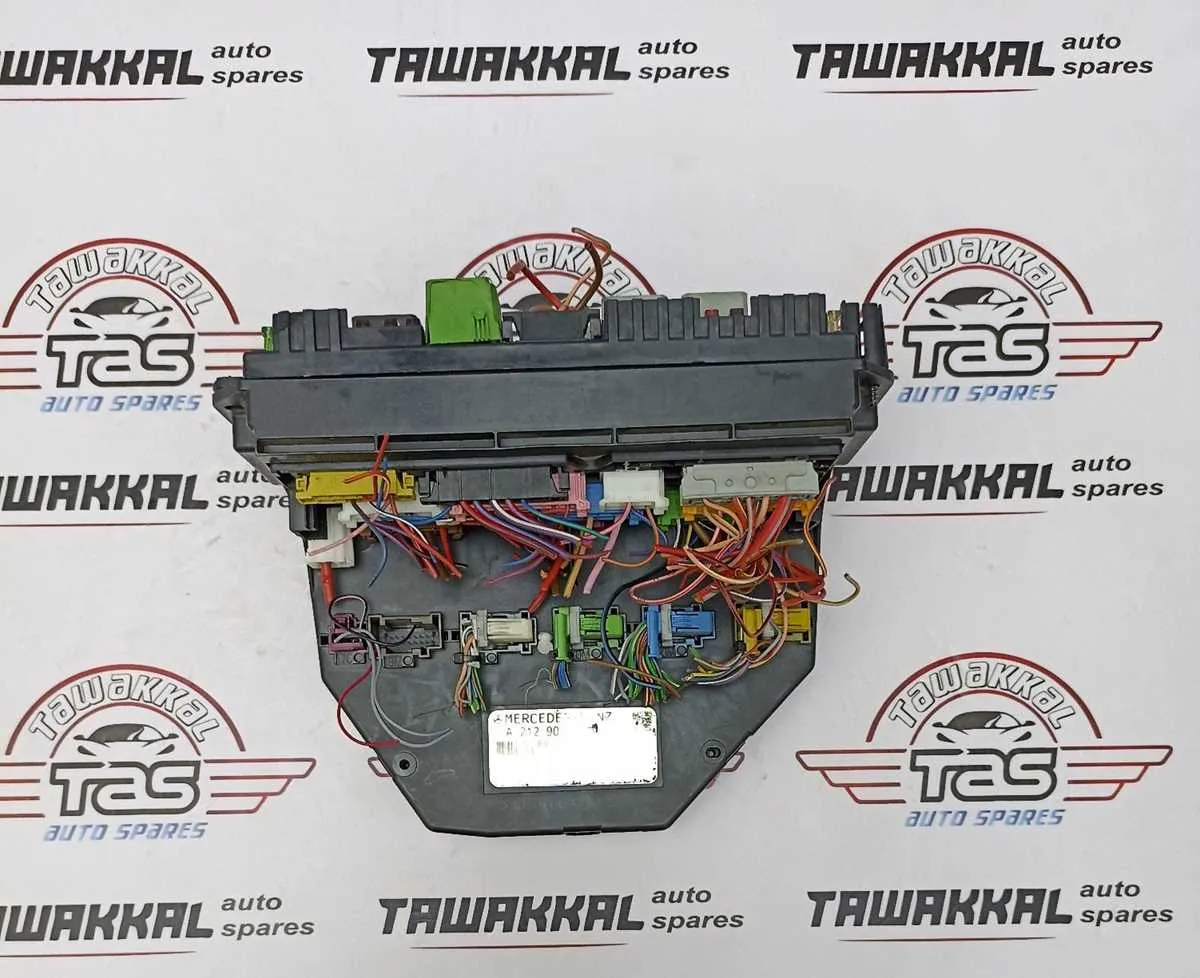
For proper functionality of your car’s electrical systems, knowing the layout of the main connection panels is essential. These panels, which control key elements such as lighting, power distribution, and critical sensors, require attention when troubleshooting or replacing fuses. By understanding the precise arrangement of each circuit, you can easily identify the malfunctioning components.
Start by locating the central unit typically positioned under the dashboard or in the engine compartment. Once you’ve identified the panel, refer to the provided guide that maps out each terminal’s function. This ensures that any replacement or repair can be done with minimal risk of further damage or incorrect installations.
Check the system specifications for your particular model to confirm the exact fuse ratings and positions. Using the wrong amperage for a fuse can lead to system failures or even cause fire hazards. Always double-check the amperage requirements listed for each electrical segment.
For convenience, consider using a multimeter to test the functionality of each circuit. This tool helps detect faulty connections without the need for excessive disassembly. Keeping a reference chart handy will streamline the process, saving you time and reducing the likelihood of errors.
Maintaining a clear understanding of the vehicle’s electrical panel structure will empower you to handle maintenance tasks more effectively, ensuring long-term reliability and safety for your car’s electrical systems.
Electrical System Layout
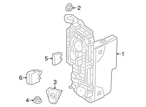
Locate the main distribution unit under the dashboard for easy access to electrical components. The layout consists of multiple rows of connection points, each responsible for specific systems. Check the top cover for identification labels of each circuit; this will help in pinpointing the exact area requiring attention.
Important: Always disconnect the power supply before inspecting or replacing any connections. Use a multimeter to verify power flow across individual terminals, ensuring correct operation.
Recommendation: For high-priority systems like lighting or engine control, focus on the central area of the setup. These circuits are often located in the middle section of the unit, with more critical systems positioned near the primary busbar.
If issues arise, refer to the marked color codes and numbering system. Each connection corresponds to a unique number that matches the vehicle’s manual for further troubleshooting. Use a non-contact voltage tester to confirm there is no active current before handling individual terminals.
Tip: When reassembling, ensure all covers and clips are securely fastened to prevent accidental disconnections during vehicle operation.
Identifying Electrical Component Locations
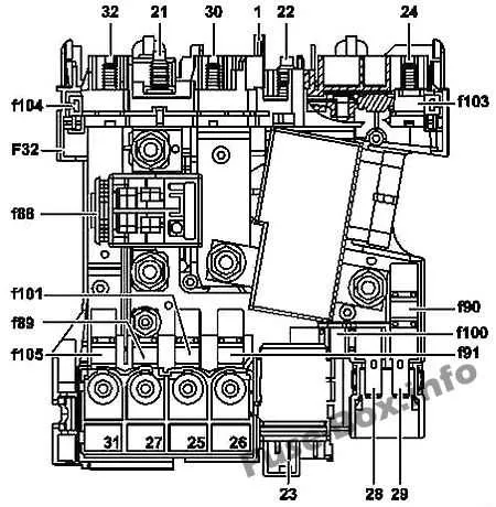
To access the electrical panel for vehicle systems, begin by locating the primary compartment, typically found beneath the dashboard on the driver’s side. This area usually contains essential fuses for the majority of functions within the cabin.
- The first access point is often behind a panel near the driver’s seat, which can be removed using a flat tool or screwdriver. Look for a rectangular or square-shaped cover.
- In some models, a secondary compartment may be located near the engine bay. This can usually be found near the battery or along the side of the engine compartment, protected by a hinged lid.
- Check beneath the dashboard on the passenger side if the driver’s side area doesn’t have the necessary components. Often, a small storage compartment hides the wiring elements.
When searching for connections related to cabin climate, infotainment, or security systems, ensure the unit behind the glovebox is carefully checked. This space holds several critical relays and protection components.
- Start by opening the glove compartment, and remove any contents for unobstructed access.
- Pull down or remove the trim panel to expose the compartment’s inner elements.
- Inspect for a series of connected relays and links, often housed in a modular setup that can be replaced individually.
If problems persist, refer to the vehicle’s manual for specific identification numbers corresponding to each section for a more efficient troubleshooting process.
Step-by-Step Guide to Reading the Electrical Layout
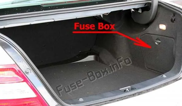
1. Locate the schematic for your vehicle’s electrical connections. This may be found in the manual or on a label inside the cabin or engine compartment.
2. Identify the symbols used for each component. These are usually standardized and represent various electrical systems like lights, engine, or air conditioning. Familiarize yourself with these codes before proceeding.
3. Find the numerical references that correspond to each component. The numbers will help you identify specific relays, connectors, or circuits that control particular vehicle systems.
4. Trace the circuit paths. They will usually be shown as lines, often in different colors, connecting various parts. Understanding the flow of electricity can guide you in diagnosing issues.
5. Check the color coding. Colors often indicate the type of connection or purpose of the circuit, such as blue for lighting or red for main power. Be sure to cross-reference the color coding with the key provided.
6. Inspect the condition of the components listed. If a part is marked as malfunctioning or a relay is burned out, you’ll know where to focus repairs or replacements.
7. Use a multimeter or tester to confirm any suspected faults in the system based on your layout understanding. Ensure all parts are in working order before concluding your inspection.
Common Electrical Issues and How to Troubleshoot
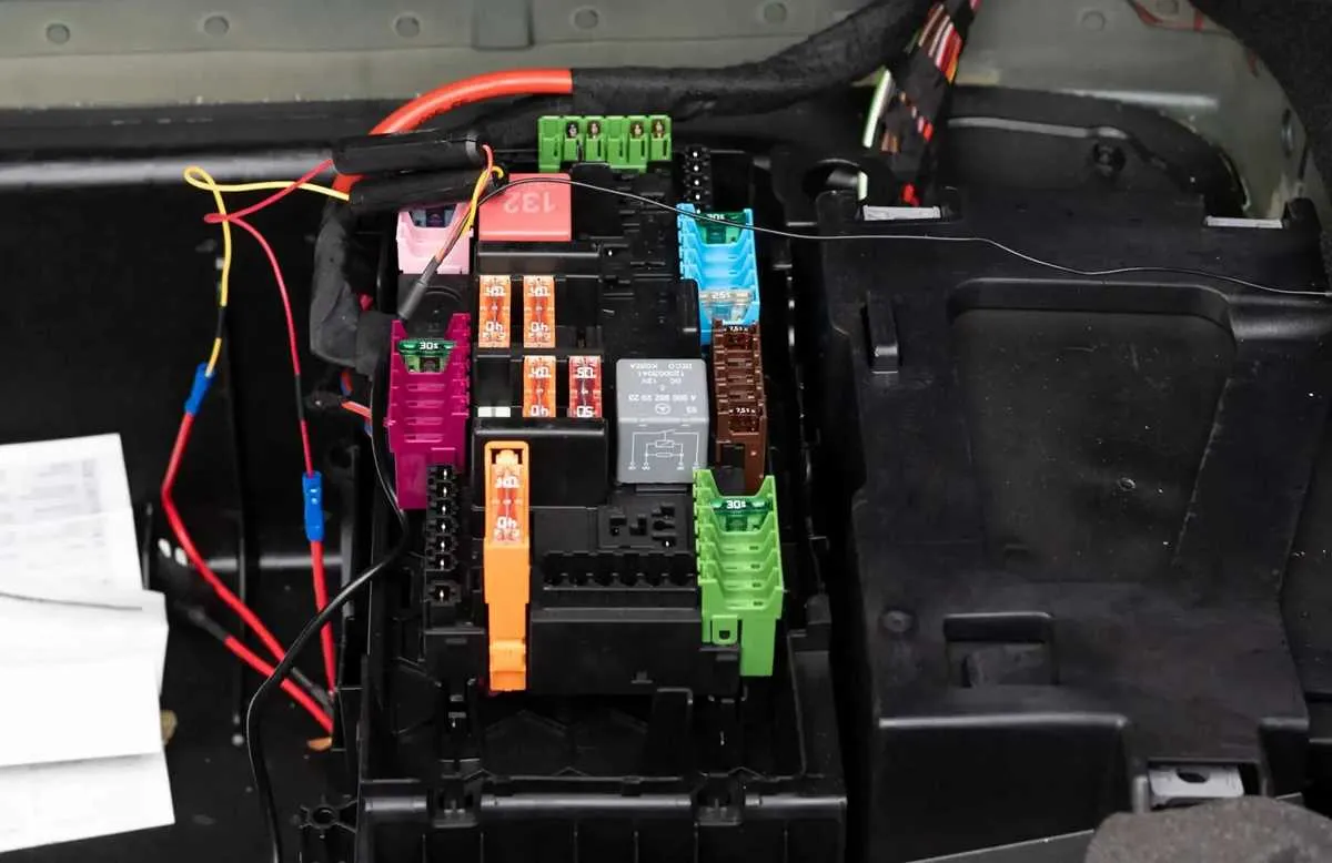
Start by identifying any non-working components in the vehicle. Electrical problems often stem from either a broken connection or an overloaded circuit. If any device isn’t functioning, check the corresponding terminals to ensure they are not corroded or loose. Use a multimeter to test the voltage levels at the terminals. A reading significantly lower than expected indicates a potential issue with the power supply or connection.
If you’re dealing with inconsistent operation, inspect each related component for any signs of wear. Wires that are frayed or damaged can lead to intermittent power disruptions. Look for any obvious signs of heat damage near connectors, which can suggest a short or overload situation. In case of such issues, replacing the affected wire or connection should resolve the problem.
In situations where multiple systems fail at once, consider a more centralized issue such as a blown relay or interrupted main power line. For this, consult the system’s main control unit to verify the integrity of all key connections. Using a schematic, trace the power flow from the source to the affected systems to locate where the interruption occurs.
Before replacing any components, ensure that the vehicle’s power is completely off. If you’ve already replaced faulty parts but the issue persists, it may be worth checking the grounding connections to ensure they are solid. A poor ground connection often causes erratic behavior in electrical systems.