Ensure a reliable connection for the automatic climate control system by following these precise steps. First, identify the main power sources and connect them to the correct terminals, ensuring that each wire is securely attached and properly insulated. Pay particular attention to the voltage ratings and amperage limits of each component to avoid potential system failures or malfunctions.
For optimal performance, use marine-grade cables, which provide better resistance to corrosion, especially in environments with high humidity. Make sure to double-check the polarity of each wire before finalizing the connections to avoid damaging sensitive equipment. Proper grounding is essential; connect the grounding wire directly to the vessel’s metal structure to minimize electrical interference.
Test the system thoroughly after installation to confirm that each component is receiving the correct amount of power and is operating smoothly. If any inconsistencies are detected, retrace the connections and verify that all components are compatible with the power supply.
Always follow the manufacturer’s guidelines for each component, and if uncertain about the installation process, consider consulting a professional electrician. A well-executed setup will ensure the long-term functionality of your climate control system.
System Connection Overview
Ensure that the charge controller and batteries are properly linked using suitable cables. Proper placement of the isolator is crucial to prevent unwanted discharge or charge issues.
When connecting the alternator, it is important to use a high-quality diode or relay for efficient power transfer. Make sure that all connections are tight and well-insulated to avoid any voltage loss.
Verify that each battery is wired in parallel or series, depending on the voltage needs of the system. This guarantees optimal power distribution across all components. Also, check that the isolator or relay operates based on the charging voltage thresholds, typically around 13.3V to 14.7V for standard lead-acid batteries.
Key tips: Use a fuse or circuit breaker at the power entry point to safeguard the entire system from potential short circuits. Consider using a monitoring device to regularly assess the charging performance and ensure it meets the required standards for your equipment.
Note: For systems with multiple power sources, ensure that each source is properly monitored to prevent overcharging or undercharging, which could damage the batteries or shorten their lifespan.
How to Connect an Automatic Charging Relay to Dual Battery Systems

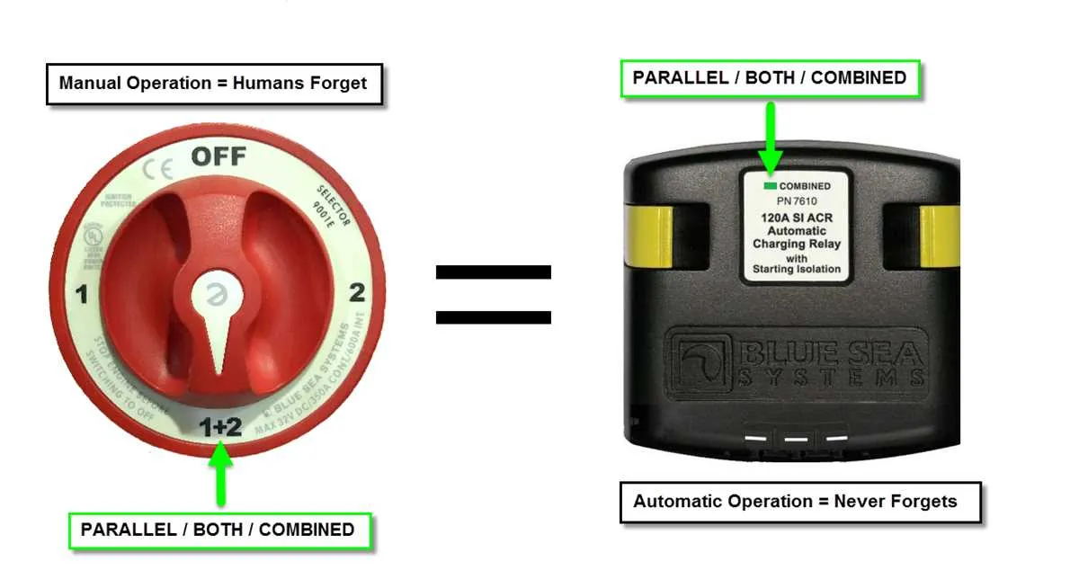
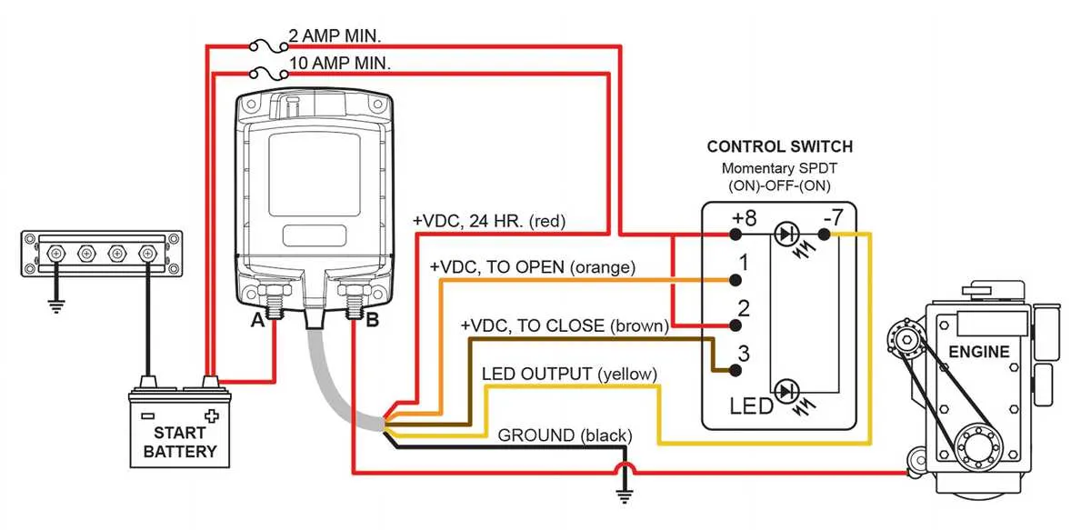
For seamless integration of an automatic charging relay with a dual battery setup, ensure the correct positioning and secure connections to maximize battery life and charging efficiency. Begin by connecting the primary battery’s positive terminal to the “input” terminal on the relay. Then, attach the secondary battery’s positive terminal to the “output” terminal. The negative terminals of both batteries should be grounded to the vessel’s metal frame or a dedicated ground bus.
To facilitate proper charging, connect the relay’s sensing terminal to the primary battery’s positive terminal. This ensures that the relay activates and directs charging power to the secondary battery only when the primary battery reaches a specific voltage threshold.
Next, connect the ignition switch to the activation terminal of the relay, allowing it to open and close based on engine status. The relay will disconnect when the engine is off, preventing potential drain on the secondary battery when it is not being charged.
Double-check the wire gauge to ensure it supports the required current capacity. Use marine-grade wire and terminals to prevent corrosion and ensure long-lasting performance in marine environments. Properly insulate all exposed wiring to avoid short circuits and ensure safety.
Step-by-Step Installation Instructions for Automatic Charging Relay
1. Start by disconnecting the negative terminal of both batteries to ensure safety during installation. Make sure the batteries are not connected to any power source.
2. Mount the relay unit in a dry, secure location close to the battery banks. Ensure it is positioned to minimize wire lengths and avoid potential damage from water or vibration.
3. Attach the main input cable from the primary power source to the relay’s designated “input” terminal. Use the appropriate gauge wire for your setup to handle the expected load. Tighten the connection securely to prevent any loose contacts.
4. Connect the “output” terminal of the relay to the second battery’s positive terminal. Again, use a wire size that matches the power requirements and make sure the connection is tight to avoid any potential issues.
5. Secure the control wire from the relay’s “sense” terminal to the positive terminal of the primary battery. This wire monitors the charge status of the main battery to control the relay’s operation.
6. The ground connections for both units should be routed to a solid negative bus or directly to the main battery’s negative terminal. Ensure all grounds are clean and free from corrosion.
7. Once all connections are completed, double-check that all wires are properly insulated and that no exposed wires could cause short circuits. Make sure everything is firmly secured and free of movement.
8. Reconnect the battery terminals, starting with the positive side, then the negative. Test the system by checking if the relay engages as the primary battery charges and disconnects when voltage levels are sufficient.
9. After successful testing, install the cover or casing for the relay to protect it from environmental factors.
Troubleshooting Common Electrical Issues in Marine Systems

Ensure proper battery connections first. A loose or corroded terminal can cause voltage drops, leading to poor system performance. Inspect the terminals regularly and clean them to ensure a secure connection.
Check for faulty relays. If a relay fails, it can prevent the alternator from properly charging the batteries, leaving them undercharged. Test relays with a multimeter to confirm they are working as expected.
If the system shows intermittent charging, inspect the control panel for issues. Sometimes, damaged components within the panel can result in an unreliable charge transfer between the batteries. Perform continuity tests on all circuits connected to the panel.
Verify the integrity of the battery isolator. If this component is malfunctioning, the batteries may not be isolated correctly, causing both batteries to discharge at the same rate. Ensure that the isolator switches effectively between batteries, allowing for optimal power distribution.
- Test voltage across terminals while the engine is running. A healthy alternator will show 13.8V to 14.4V. If the voltage is lower, check alternator output.
- Ensure correct polarity between the primary and secondary power sources. Reversed polarity can cause system failure.
- If no charge is reaching the secondary battery, test the diode connection and replace if damaged.
Lastly, always refer to your system’s manual for specific troubleshooting steps and replace any worn-out or damaged components promptly to prevent further damage.