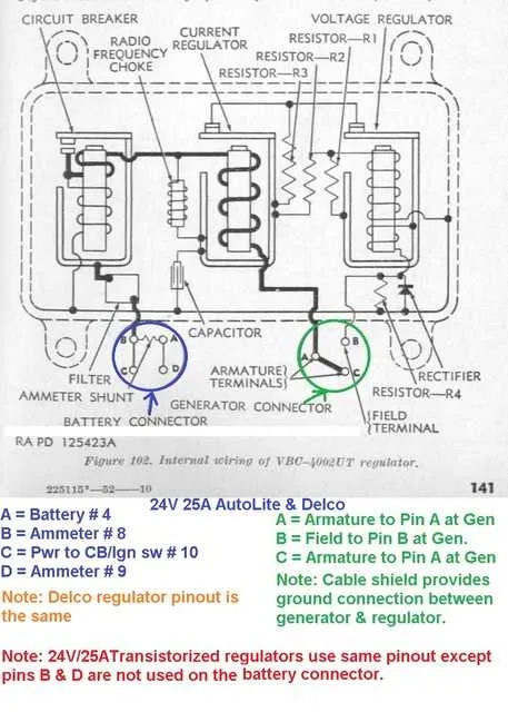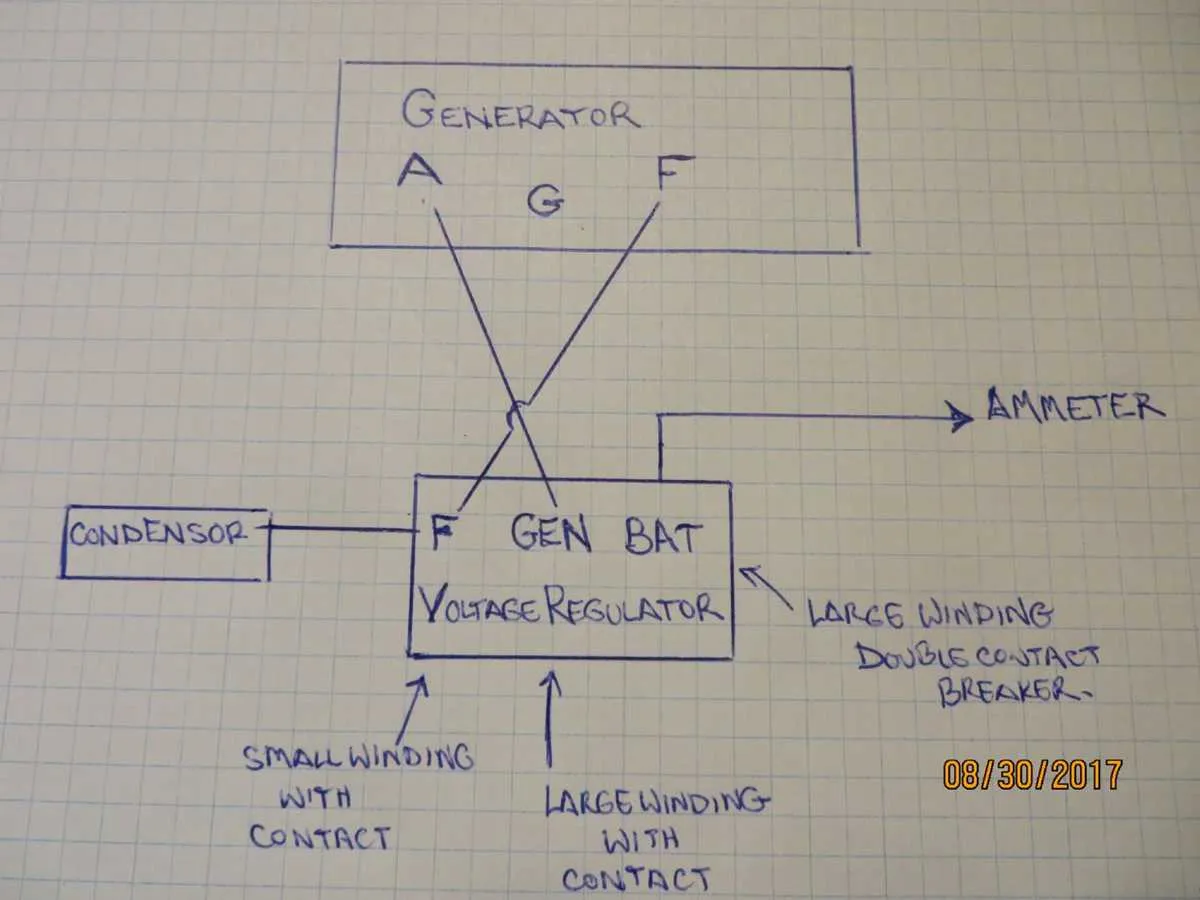
For efficient performance of the classic utility vehicle’s charging system, install the control module adjacent to the generator housing, typically mounted on the inner fender panel near the firewall. This positioning ensures optimal cable routing and ease of maintenance while minimizing electrical interference.
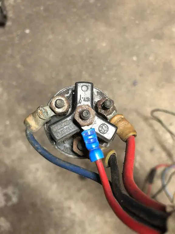
Connection points on this device include terminals for the battery feed, ground, and output to the ignition system. Correct identification and secure fastening of these leads are critical to maintain proper current flow and avoid overcharging the battery.
Reference illustrations often highlight the component’s exact mounting bracket and the corresponding wire harness layout, which align with the frame and body structure of the early post-war military-style jeep. Following these guides will help prevent miswiring and potential damage to sensitive electrical parts.
Routine inspection of the controller’s fasteners and terminal integrity is recommended to preserve system reliability under rugged conditions. Replacement parts should match original specifications to maintain the historic vehicle’s operational authenticity.
Generator Control Unit Placement Illustration

The control device responsible for managing electrical output is mounted directly on the firewall, to the right side of the engine compartment when facing forward. It is secured near the starter solenoid, often attached to a metal bracket that allows easy access for maintenance. Wiring from the generator leads directly into this unit, with terminal connections clearly labeled for battery, field coil, and ground.
For clear identification, follow the main harness from the alternator output; the device is positioned just above the frame rail, behind the radiator support. This setup ensures efficient voltage regulation and facilitates straightforward troubleshooting. Avoid confusion with other nearby relays or fuses by noting the distinctive rectangular metal casing with ventilation slots.
When replacing or inspecting, disconnect the battery first and confirm the unit’s attachment points: typically two screws mounting it to the firewall panel. Ensure all connectors are firmly seated to maintain consistent electrical flow and prevent voltage irregularities during operation.
Identifying the Voltage Regulator on CJ2A Wiring
To locate the electrical control unit responsible for maintaining a stable output, check near the generator. This component is typically mounted on the firewall or attached to the engine bay, close to the charging system. It will usually have three connections: one for the battery, one for the generator, and one for the ground. The cover is often metal, and it features either two or three screws securing it in place.
Trace the wires from the charging system; the component should be found along the main path that connects the alternator or generator to the rest of the electrical system. Often, it’s located to the side or slightly behind the engine, attached to a bracket or metal mounting point. In some configurations, it might be positioned near the battery, close to other power distribution elements.
If you’re unable to find it visually, refer to the wiring diagram of the system, focusing on the connection points between the generator and the battery to ensure you’re identifying the correct unit.
Step-by-Step Guide to Accessing the Voltage Controller

Start by ensuring the vehicle is off and the battery is disconnected. This step prevents any electrical shocks or short circuits while you work on the components.
Locate the engine compartment where the electrical components are housed. Typically, the unit will be positioned near the engine block, often on the driver’s side. Look for a small metal box or cylindrical component mounted on a bracket or directly to the firewall.
Use a wrench to remove any securing bolts or fasteners. You may need to use a ratchet tool for tight spaces. Once the component is loose, carefully pull it away from its mount, exposing the wiring attached to it.
Gently disconnect the wiring harness. Pay close attention to the orientation and connections of each wire, as this will be crucial for reinstallation. Use a multimeter to check for any power or residual charge before proceeding.
If necessary, remove any additional components obstructing access, such as hoses or covers. This will allow for better visibility and ensure you don’t damage any parts during the process.
After gaining access, inspect the wiring connections and check for any corrosion or wear. This is a good time to clean or replace any damaged parts to ensure proper function when reinstalled.
Reinstall the component by reversing the steps. First, reconnect the wiring securely, ensuring there are no loose connections. Then, reattach the component to its original mounting bracket or location.
Finally, reconnect the battery and test the system to ensure everything is functioning correctly. Double-check for any unusual sounds or electrical issues after powering up.
Connecting the Voltage Control Component in the Electrical System
Ensure proper wiring and placement of the electrical control device within the circuit. The device should be securely attached to the frame, typically near the engine compartment, where it can maintain proper heat dissipation.
- First, identify the two main connections: the input wire from the battery and the output wire to the charging system.
- Make sure the input wire is securely connected to the positive terminal of the battery. This provides the necessary power for the system.
- The output wire should be routed to the alternator or charging unit, ensuring a strong connection to the field terminal.
- Double-check the ground connection, which must be attached to a clean, unpainted metal surface on the frame to ensure minimal resistance.
Verify all connections with a multimeter to confirm that they are properly established. The device should only be installed after ensuring there is no voltage or current flowing through the circuit. Once connected, inspect for any signs of wear or corrosion on the wires and terminals.
- When securing the device, use vibration-proof mounts to prevent loosening due to engine movement.
- Ensure the components do not obstruct airflow, which could cause overheating or inefficiency.
Lastly, check the system after installation for consistent performance. The device must be able to regulate the flow of electricity within the system, ensuring that all components receive stable power for optimal functioning.