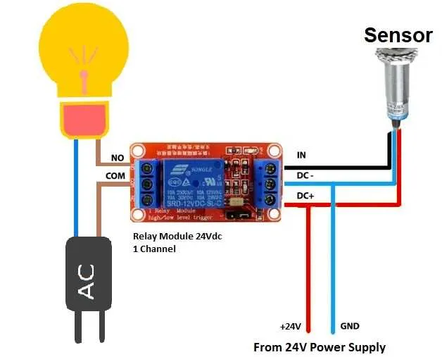
For reliable operation of low-voltage switching systems, ensure correct placement of connections to prevent faults. Start by linking the positive terminal of your power source to the switch’s input terminal. Then, connect the output side of the switch to the device or system being controlled. It’s crucial to maintain a clean, corrosion-free connection for longevity and optimal performance.
Power and Grounding: Always use properly rated cables to manage the current load. The ground connection should be secured tightly to avoid potential interference with the system’s operation. Ensure the power source is stable to minimize the risk of system malfunctions.
Load Control and Safety: When wiring the output device, check for any protective components such as fuses or circuit breakers to prevent overcurrent. Incorrect connections can lead to damage or malfunction, so double-check the configuration before powering up. Following these steps ensures an efficient and safe setup.
Connecting a 24-volt Switch
To connect a 24-volt switch for controlling higher power devices, begin by using a coil rated for 24V. The coil terminals should be connected to the appropriate power source, ensuring correct polarity–positive to the coil’s positive terminal and negative to the coil’s negative terminal.
For the switching circuit, identify the common, normally open, and normally closed contacts on the component. The common terminal should be linked to the power input, while the normally open contact connects to the load device. This way, the circuit will be complete when the switch is activated.
Ensure that the load device, whether it’s a motor, light, or other equipment, is connected to the normally open terminal. Once the coil is energized, the common terminal will connect with the normally open terminal, allowing current to flow and powering the connected device.
For safe operation, always verify the current rating of both the switch and the load device. Using appropriate fuses or circuit breakers will help protect the circuit from overcurrent situations. It is also crucial to verify the grounding of the entire setup to prevent electrical faults.
Understanding the Basic 24v Relay Connections
To successfully wire a 24V switching component, ensure proper connections between the control circuit and load circuit. First, identify the coil terminals that will activate the mechanism when voltage is applied. These are typically marked as the input terminals.
Next, connect the output terminals to the load that will be controlled, such as a motor or light. Pay attention to the switching configuration–whether it’s normally open (NO) or normally closed (NC)–to ensure the system operates as intended when the current flows through the component.
For reliable operation, it’s crucial to protect the system from overcurrent situations by adding a fuse or circuit breaker in the control circuit. This prevents potential damage to sensitive components.
Tip: Ensure that the coil voltage matches the control signal to avoid malfunctions. Also, check the rated current for both the input and output sides to guarantee the system’s longevity and efficiency.
Important: Verify that all connections are secure and that there is no risk of short-circuiting the components, which could lead to failures or hazards.
How to Connect a 24V Switch for Automotive Applications
Start by identifying the control circuit and power components. The first step is connecting the coil terminals to the vehicle’s electrical system, typically using a direct current source. Ensure the positive lead from the power supply is connected to one coil terminal, while the negative is routed to a control switch or ground. This will energize the system when activated.
Next, link the common terminal of the switching component to the load’s positive input. This could be the motor, fan, or any other device you wish to operate. The other terminal of the load should connect to the power source, ensuring correct polarity to prevent short circuits.
If the setup includes a control mechanism, such as a manual or automatic switch, it should be connected to the coil’s ground side. When this switch is toggled, it will activate the system, allowing current to flow through the load and operate as intended.
Make sure to install a flyback diode across the coil terminals to prevent voltage spikes when deactivating the system. This protects the circuit from potential damage caused by inductive loads.
Common Connection Mistakes and How to Avoid Them
Ensure proper identification of pin assignments before connecting components. Incorrectly matched terminals can cause operational failure or even damage to the system.
- Incorrect polarity: Always verify the positive and negative terminals. Reversing connections can result in malfunction or electrical short.
- Overloading contacts: Never exceed the current rating of the component’s terminals. Check the specifications to ensure compatibility with the connected load.
- Insufficient insulation: Exposed wires can lead to short circuits. Use appropriate insulation or heat shrink tubing to secure connections.
- Loose connections: Tighten screws and fasteners properly to avoid loose contacts, which can cause intermittent faults or complete failure.
Double-check each connection before powering the system. A small mistake in the initial setup can lead to significant performance issues or damage.
- Wrong voltage supply: Ensure the power source matches the component’s requirements. Using the wrong voltage may cause overheating or failure of sensitive components.
- Improper grounding: A stable ground connection is essential for proper operation. Ensure the ground wire is securely connected to prevent erratic behavior or safety hazards.
- Using inappropriate connectors: Choose connectors that match the gauge of your wires and ensure they fit tightly to prevent poor contact.