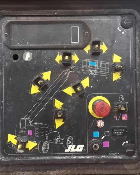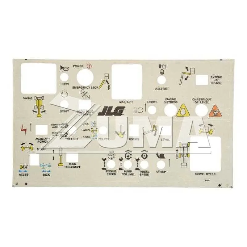
Always start by disconnecting the power source before accessing any electronic components. Locate the operator interface near the platform; it typically includes a multi-position joystick, toggle switches, and status indicators. Each element corresponds to specific hydraulic and electrical functions that must be clearly understood before troubleshooting.
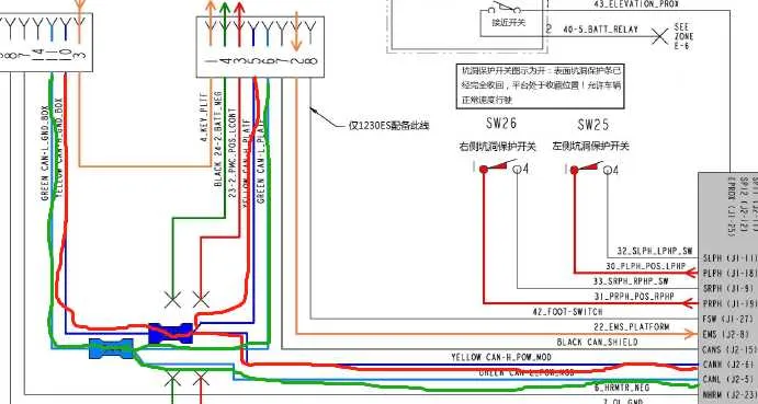
The layout includes a central joystick module wired to the main circuit board through a harness of color-coded leads. Each wire is labeled with alphanumeric codes matching the schematic provided in the technical manual. For example, a wire marked “G1” may indicate a ground circuit related to horizontal movement.
Emergency stop circuits are usually wired in series across the red-coded leads; verify continuity using a multimeter. For directional commands, refer to the proportional solenoid valve leads, often labeled “P1,” “P2,” etc., and test voltage output from the interface when actuating the joystick.
Use the service manual to trace signal paths from input levers to the relay board. Pay attention to diagnostic LEDs, which indicate faults through blinking patterns. Understanding these indicators simplifies the isolation of failed modules, especially in the elevation and rotation systems.
Never bypass safety interlocks. Instead, identify the relevant circuit–typically routed through limit switches located at pivot points–and verify their status during operation. Replace damaged harness connectors with weatherproof equivalents to prevent future failures.
JLG Boom Lift Control Panel Diagram
Begin diagnostics by locating the joystick interface–typically positioned on the upper right of the operator console. It includes a proportional trigger for elevation and extension, plus a thumb rocker for rotation. Identify the key switch first: it selects operational modes (ground/platform). Ensure it is set to “platform” before engaging functions from the upper module.
Refer to the following map of main components and indicators:
| Identifier | Function | Location |
|---|---|---|
| S1 | Main selector for power source and mode | Upper-left quadrant |
| J1 | Motion joystick with built-in enable switch | Right-hand grip area |
| F1–F4 | Individual toggles for hydraulic functions | Central panel row |
| L1 | Status LEDs for tilt, load, and diagnostics | Top edge indicator row |
| E-stop | Emergency shutdown mechanism | Upper-central red button |
To isolate electrical faults, use the schematic label codes typically etched or printed adjacent to wiring terminals. Voltage checks across J1-X1 to X4 during joystick movement help validate proportional response. Always verify CAN line integrity between interface board and base controller via terminals labeled CANH and CANL.
Control Layout for 450AJ and 600S Models
Ensure safety and ease of use by familiarizing yourself with the operational configuration of the 450AJ and 600S machines. Both units feature a comprehensive arrangement for efficient handling and functionality during operation. Prioritize checking key components like the joystick controls, emergency stop switch, and power indicators before starting the vehicle.
Joysticks: The most crucial components are the dual joysticks, typically positioned centrally. The left joystick handles the horizontal motion and angle adjustment, while the right joystick controls the vertical movement. Ensure both joysticks are responsive and calibrated for precise operation.
Emergency Stop: Located in an easily accessible spot on the main unit, the emergency stop should be tested before each use. It’s vital to verify that it can cut power effectively in case of unexpected events.
Display Screen: Both models incorporate an integrated display that shows critical operational metrics such as battery level, system diagnostics, and error messages. A functioning screen is essential for real-time monitoring.
Buttons and Switches: Additional switches for mode selection, drive functions, and tilt adjustment are typically grouped around the main control area. Check that each button clicks into place without any resistance and the indicators light up as expected.
Maintenance Alerts: Pay close attention to any visible alerts or maintenance warnings displayed. These indicators ensure that the system remains in optimal condition and prevent malfunctions during high-risk operations.
Power Override: The override system should be tested regularly to confirm it works in case of electrical failure. This feature allows for manual operation and is essential for emergencies or troubleshooting.
Functions of Each Button, Switch, and Joystick on the Operator Console

Each button and joystick on the operator’s console is designed for specific tasks to ensure smooth operation. Understanding the function of each is crucial for efficient use and safety.
The joystick, typically central, controls the movement of the platform in multiple directions, such as raising, lowering, and extending. It also allows for horizontal movement and tilt adjustments. Pressing the joystick in one direction moves the platform, while releasing it stops the movement.
The main power button is often the first control encountered and is used to turn on the system. It must be engaged before any further actions can be taken. If this button is not activated, the equipment will remain off.
The emergency stop switch is a red button located prominently for immediate access in case of malfunction or danger. Pressing it immediately disables all functions of the machine to prevent accidents.
Directional switches, usually located on the right-hand side, control the rotation of the platform. These allow the operator to rotate the entire assembly 360 degrees horizontally, with finer adjustments made through a smaller control switch.
The lift control switches, often separate from the joystick, regulate vertical movement. There may be two distinct buttons for raising and lowering, each ensuring smooth and gradual ascent or descent.
Additional toggle switches may be used to engage or disengage the platform’s stabilizers or to activate other auxiliary systems, such as lights, horns, or alarms. Each function is clearly labeled and should only be operated when required for specific tasks.
Safety features like tilt and overload indicators are typically integrated into the display section. These visual indicators alert the operator if the platform exceeds safe operational angles or weight limits, prompting immediate corrective action.
Operators should regularly inspect all buttons and switches for wear, ensuring each responds as expected. Proper maintenance is critical for ensuring functionality, especially of safety-critical components such as the emergency stop and tilt indicators.
Troubleshooting Common Issues with Machine Indicator Lights

Check the power source first. If the display is blank or unresponsive, confirm that the main power switch is fully engaged and the battery is charged. Low voltage can cause incorrect readings.
If an indicator shows an error code, consult the operator manual to decode it. For instance, an E01 or E02 may suggest a hydraulic issue. Addressing hydraulic fluid levels or leaks can resolve this.
- Inspect the hydraulic system for any signs of leaks or damage.
- Ensure fluid levels are within the recommended range.
- Verify the condition of hoses and fittings.
For issues related to electrical components, check fuses and relays. A blown fuse often leads to non-functional buttons or indicators. Replace any damaged components to restore normal operation.
- Examine the wiring for loose connections or corrosion.
- Ensure proper grounding of electrical parts to avoid short circuits.
If the speed control light is flashing, it may signal that the platform has not reached the correct position or that a limit switch is malfunctioning. Inspect the machine’s position and recalibrate if necessary.
- Confirm the platform is level and securely locked.
- Test limit switches for functionality and adjust if needed.
In case of a malfunctioning emergency stop light, verify that the safety circuit is properly engaged. Resetting the system may be required to restore functionality. If the light remains on, check for underlying system faults such as excessive load or hydraulic pressure issues.
- Inspect safety switches and override controls.
- Test the emergency stop mechanism for any blockage or mechanical failure.
Lastly, if any warning lights persist, it’s crucial to stop operation and perform a full system diagnostic to prevent further damage or malfunction.