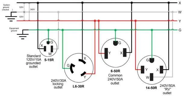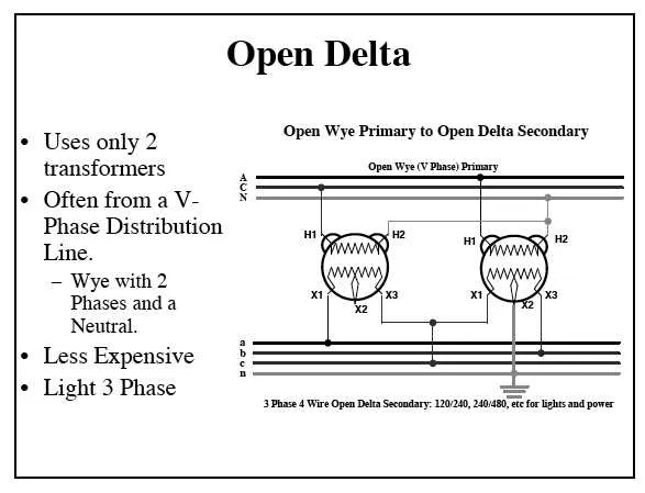
For safe and efficient installation of a three-line 240-volt setup, ensure each conductor is correctly identified and secured to its respective terminal. Use color-coded cables–typically black and red for hot lines, and green or bare copper for grounding–to maintain clarity and prevent wiring mistakes.
Verify that the power supply delivers balanced load across all three conductors, minimizing voltage drop and optimizing performance. Employ insulated connectors rated for the system’s amperage, and double-check torque specifications on all screw terminals to avoid loose contacts.
Before starting any connections, disconnect the main power source and test with a voltage detector. Follow local electrical codes for cable sizing and breaker requirements to guarantee compliance and safety. Proper arrangement of the conductors reduces electromagnetic interference and extends the lifespan of connected equipment.
3 Phase 240V Wiring Diagram
Connect three hot conductors labeled L1, L2, and L3, each carrying 120 volts relative to neutral, to the appropriate terminals on the load. Use a four-wire cable including a neutral and a ground wire for safety and proper operation. Ensure the ground is securely bonded to the equipment frame and connected to the grounding system.
For motor installations, match the line leads to the motor terminals as per the manufacturer’s configuration for the required operating voltage. Verify all breakers or fuses are rated for the combined current draw of the device. Use conductors rated for at least 75°C to comply with electrical codes.
Neutral must carry unbalanced current and be sized according to the load calculations. Install a disconnect switch rated for the total amperage, positioned within sight of the equipment for easy access. Label all conductors clearly to avoid confusion during maintenance or troubleshooting.
How to Identify and Connect Each Line in a Three-Line 240 Volt System
Always verify the voltage and sequence before making any connections. Use a reliable multimeter or phase rotation tester to determine each conductor’s role.
- Identify Conductors:
- Label the three hot wires as L1, L2, and L3 according to their test results.
- Confirm each line’s voltage relative to neutral or ground; it should read approximately 120 volts per line-to-neutral.
- Check line-to-line voltage readings to ensure they are close to 208-240 volts.
- Sequence Verification:
- Use a phase rotation meter to confirm the rotation sequence (e.g., L1-L2-L3).
- Correct rotation prevents motor damage and ensures proper operation of three-phase equipment.
- Connecting Lines:
- Match each labeled line to the corresponding terminal in the equipment or distribution panel.
- Tighten all connections to manufacturer torque specifications to avoid overheating.
- Double-check connections against the equipment’s connection chart to prevent cross-wiring.
- Safety Checks:
- Ensure all conductors are de-energized before handling.
- Use proper personal protective equipment (PPE) during testing and connection.
Step-by-Step Guide to Connecting a 3-Pole Motor Starter for 240V Supply
Begin by ensuring the power is completely disconnected before handling any cables. Identify the three incoming conductors from the power source–typically labeled L1, L2, and L3–and verify their voltage using a multimeter.
Connect each conductor to the corresponding terminal on the starter’s input side, matching the order to maintain correct rotation direction. Tighten all terminal screws securely to prevent loose contacts that could cause overheating.
Attach the motor leads to the output terminals of the starter, following the motor’s nameplate wiring instructions to ensure compatibility. If reversing the motor rotation is required, interchange any two of the three output wires.
Install the control circuit components next: connect the control transformer secondary to the starter coil, verifying that coil voltage matches the control voltage supply, commonly 120V or 240V.
Wire the start and stop push buttons in series with the coil to enable manual operation. Include an overload relay between the motor terminals and the starter coil, setting the relay to the motor’s full-load amperage to protect against overcurrent conditions.
Double-check all connections for proper torque and insulation integrity. Once confirmed, restore power and test the starter by pressing the start button; the motor should energize smoothly without unusual noises or excessive vibration.
If the motor fails to run or trips the overload, immediately disconnect power and re-inspect all contact points and relay settings. Proper assembly and calibration are essential for safe and reliable operation.
Common Troubleshooting Tips for 3 Phase 240V Wiring Issues

Always verify voltage levels between all three conductors with a reliable multimeter before proceeding. Imbalanced readings often indicate a loose connection or faulty breaker. Check terminal screws and connectors for proper tightness to prevent intermittent power loss.
Inspect insulation resistance using a megohmmeter; values below 1 MΩ suggest potential shorts or degraded cables needing replacement. Look for signs of overheating such as discoloration or melted insulation near connectors and contact points.
Ensure the neutral conductor is continuous and properly grounded to avoid floating neutral problems that cause erratic equipment behavior. Confirm that all circuit breakers and fuses are rated correctly for the load to prevent nuisance trips.
Measure current draw on each conductor with a clamp meter. Significant disparities often point to unbalanced loads or wiring faults. Verify that load devices are connected following manufacturer specifications to avoid reverse polarity or miswiring.
Use thermal imaging to identify hotspots in panels and connections which can indicate high resistance points needing immediate attention. Replace any damaged or corroded terminals to maintain conductivity and system stability.