When configuring a system to handle three distinct voltage levels, ensure that you correctly follow the right connection strategy to maintain efficiency and safety. The key to a stable setup lies in understanding the relationship between the primary and secondary components and how they interact across multiple lines.
First, verify that your power sources are balanced, ensuring that the inputs remain within acceptable ranges to avoid overloading. The method you use to link the coils will determine the load handling capacity and how effectively the system can deliver power to various parts of your installation.
Next, consider the core arrangement. A proper alignment of winding taps can significantly influence your voltage conversion. Configuring the right number of turns will directly impact the distribution of current through each leg of the setup, preventing unbalanced loads.
Finally, check the grounding and safety protocols to prevent damage due to faults or irregular currents. This step is crucial in high-voltage environments, as the risk of short circuits or electrical fires can be minimized with the proper grounding techniques.
3-Phase Electrical Configuration
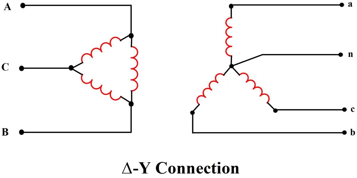
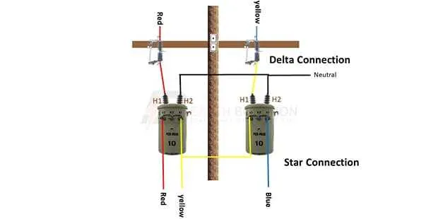
For optimal performance, always use a star or delta setup when connecting multiple circuits to a high-voltage system. In the star connection, the center point is grounded, while the outer terminals are linked to different conductors. This minimizes the risk of imbalance and ensures stable operation under varying loads.
When using the delta approach, each conductor connects to the adjacent terminals in a closed loop. This type of system provides a more robust power supply but requires careful monitoring of the load distribution to avoid overheating.
In a well-balanced system, make sure to follow correct conductor size specifications to prevent energy loss. Calculating the proper insulation level for each conductor ensures that the system runs efficiently and safely. For reduced harmonic distortion, use a center-tapped neutral, ensuring proper voltage distribution across each conductor.
Always verify the integrity of connections with a multimeter before activating the circuit. Regular maintenance and inspection of all components are essential to avoid unexpected failures and ensure long-term reliability. Using fuses and circuit breakers in critical points offers extra protection against surges.
Key Tips:
1. Ensure uniform load distribution.
2. Use properly rated components to handle power spikes.
3. Follow safety protocols when grounding to avoid electrical faults.
Understanding the Primary and Secondary Windings in 3-Phase Electrical Systems
When working with a 3-phase electrical setup, the roles of the primary and secondary coils are crucial for the effective transfer of energy between circuits. Below are key points that should be kept in mind:
- The primary coil is responsible for receiving power from the source and creating a magnetic field that induces voltage in the secondary coil.
- The secondary coil delivers the energy to the load, providing the necessary voltage to power devices or systems.
- Both coils should be carefully matched in terms of turns ratio to ensure voltage conversion is accurate and efficient.
Here are a few practical considerations for the windings:
- Voltage Rating: Ensure the voltage rating of both coils matches the system’s requirements. Misalignment in voltage can lead to inefficiency or even equipment damage.
- Current Handling: The primary winding often carries higher current, so it must be designed with thicker conductors compared to the secondary, which typically handles lower current.
- Insulation: Proper insulation is essential to prevent short circuits and ensure safety in both windings. The insulation material must be chosen based on operational conditions such as temperature and potential exposure to environmental hazards.
- Load Characteristics: The impedance characteristics of the secondary winding will influence the system’s load performance. It should be designed to handle the maximum expected load without overheating or excessive voltage drop.
In sum, careful attention to the primary and secondary winding design, including turns ratio, voltage handling, current capacity, and insulation, ensures safe and efficient operation in any 3-phase electrical setup.
Wiring Configuration for Star and Delta Connections in 3-Phase Transformers
For optimal performance, the selection of star or delta configuration depends on load requirements and voltage characteristics. In star systems, the neutral point is accessible, making it ideal for low voltage applications or where grounding is required. In contrast, delta systems are best for balancing loads, providing higher line-to-line voltage for industrial equipment.
Star Configuration: The primary windings are connected to a common point, offering a balanced system with reduced voltage stress on the winding. The neutral is available for systems where unbalanced load distribution might occur, or when grounded connections are necessary. This setup typically provides a lower line-to-neutral voltage than the line-to-line voltage.
Delta Configuration: This setup connects the ends of the windings in a triangular loop. It does not provide a neutral point, making it ideal for applications where grounding is not needed. This configuration handles larger load demands efficiently due to its ability to maintain constant voltage levels and the absence of neutral points which could lead to voltage imbalances in some systems.
Key Differences: In a star connection, the line-to-neutral voltage is less than the line-to-line voltage. For delta, the line-to-line voltage is the same as the winding voltage, leading to higher efficiency in delivering power to heavy machinery. Understanding these distinctions is crucial for selecting the appropriate configuration for specific electrical needs.
Practical Steps for Correctly Wiring a 3-Phase Power Distribution System

Start by identifying the voltage ratings of the equipment and ensuring that they match the incoming supply. This will determine the necessary connection configurations.
Connect the primary side terminals of the unit to the supply lines. Ensure that the input terminals are labeled correctly, following the manufacturer’s instructions. The wiring should be secured with high-quality insulation materials to prevent any accidental shorts.
Ensure that the neutral line is properly grounded and connected to the center tap of the system if applicable. This is crucial for stable operation and safety.
Use correctly sized conductors for the connections. Gauge selection depends on the total current load and the length of the wire run. Improper sizing can lead to overheating and power loss.
If the setup includes multiple units in a series or parallel configuration, check that each one is correctly linked according to the total load requirement. Verify that load balancing is achieved across all elements to avoid overloading any single segment of the circuit.
After connecting, double-check that all terminals are torqued correctly, ensuring tight connections. Loose terminals can lead to arcing, heat buildup, or system failure.
Finally, perform a full test under load to ensure everything is operating within the required specifications. Monitor voltage levels, currents, and temperatures during operation to confirm that the system is functioning properly without any signs of stress.