When integrating protective switches into your electrical system, ensure that connections are precise and meet safety standards. Properly linking the protection units will prevent potential hazards like overcurrents or short circuits, significantly reducing the risk of fire or equipment damage.
First, identify the correct terminals on your protective unit. The device typically has a dedicated line and load terminal for proper connection. Always ensure that the incoming and outgoing wires are securely tightened to avoid any loosening during operation, which could lead to overheating or malfunction.
Use appropriate wire sizes based on your electrical load to ensure the protection unit functions effectively. Under-sizing or over-sizing wires can reduce the protection’s reliability, so adhere to the manufacturer’s recommendations for wire gauge and installation practices.
When setting up the connections, verify the polarity of the incoming power lines to ensure proper current flow. In cases where the wiring is reversed, the protection device might not operate as intended, leading to undetected issues.
Electrical Protection System Connection Guide
Ensure proper placement of the protective devices between the power supply and the connected load. When installing, verify that all terminals are securely attached and insulated, preventing any exposed connections that might result in unwanted energy discharge. The unit should be positioned in a manner that allows easy access for maintenance but avoids environmental hazards like moisture or excessive heat.
Proper conductor sizing is crucial. Use conductors that meet the ampacity rating of the system, ensuring they can carry the load without risk of overheating. Ensure that the connectors are tight enough to avoid resistance build-up, which could cause a potential malfunction.
Check the operational testing function after installation. Simulate an interruption by using a tester to confirm that the system responds to simulated hazards appropriately. If the device fails to activate or reset properly, recheck the wiring connections and ensure no loose contacts are present. After confirming correct operation, label the device for easy identification during future inspections.
Installation location must be chosen with care. Protect it from mechanical damage by positioning the device in a protected, stable environment. Always confirm the manufacturer’s guidelines to ensure compatibility with the installation environment.
How to Connect Safety Switch to the Electrical Panel

Start by turning off the main power supply to prevent any electrical hazards. Ensure that the panel is properly grounded before proceeding with the installation.
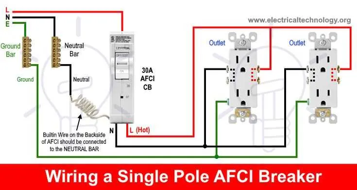
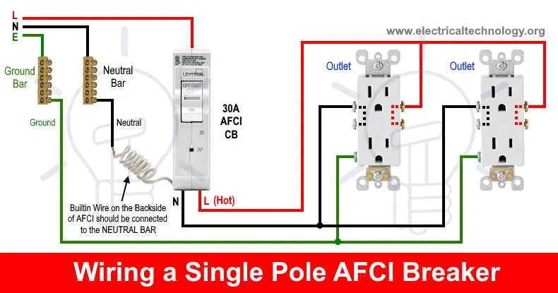
Begin by attaching the neutral wire from the safety switch to the neutral bus bar in the panel. This ensures proper current flow and avoids potential issues.
Next, connect the hot wire from the safety device to an available slot on the breaker panel, matching the amperage rating of the unit. Tighten the connection securely to prevent any loose connections that could cause overheating.
For the grounding process, connect the grounding wire to the dedicated ground bus bar in the panel. Double-check that the wire is properly secured and not exposed to any potential wear.
Once all wires are connected, close the panel cover and ensure that all connections are firm. Finally, switch on the power and test the functionality of the safety device by activating the test button to confirm that it operates as expected.
Understanding the Components in an Electrical Safety Protection System

Ensure all parts are correctly chosen to maximize protection against electrical hazards.
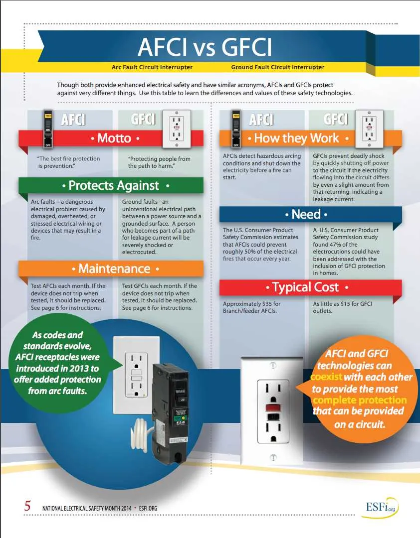
- Detection Mechanism: This component identifies irregular electrical patterns, such as unintended currents or power surges, which could potentially lead to dangerous conditions.
- Interruption Unit: Designed to automatically stop the flow of current once an anomaly is detected. It acts swiftly to minimize the risk of fire or damage to electrical appliances.
- Grounding System: This is essential for redirecting excess energy safely to the ground, preventing dangerous build-ups in the electrical network.
- Connection Points: Ensure tight and secure connections throughout the system to prevent failures due to loose or faulty terminals. Regular maintenance and inspection of these parts are crucial for consistent performance.
- Control Mechanism: A manual or automated switch that enables you to engage or disengage the protection unit as needed, providing control over the electrical environment.
When selecting a system, ensure each component is rated for the specific application, keeping in mind voltage, current, and environmental factors to guarantee reliable operation.
Common Mistakes When Installing Safety Switches
Ensure that the connections are made securely, as loose or poorly tightened terminals are a primary cause of malfunction. Double-check that all connections are in the correct order to avoid short circuits or misalignments. Pay close attention to the neutral wire placement; it should not be connected to the ground terminal, as this can create hazardous conditions.
Verify that the wiring is the correct gauge for the current load. Using an undersized conductor can lead to overheating and potential failure of the protective device. Additionally, never use old or worn-out cables, as this can compromise the entire system’s safety.
Avoid mixing wires from different circuits when installing protective devices. Every protection unit should have its dedicated wiring and not share paths with unrelated circuits. This will ensure that each circuit is independently protected in case of an issue.
Check for proper grounding. Insufficient or improper grounding of the unit can cause erratic behavior or failure to activate under fault conditions. Always test the ground connection before finalizing the installation.
Lastly, confirm that the device’s rating matches the installation requirements. Overestimating or underestimating the capacity can result in improper function, either causing nuisance tripping or inadequate protection against electrical faults.