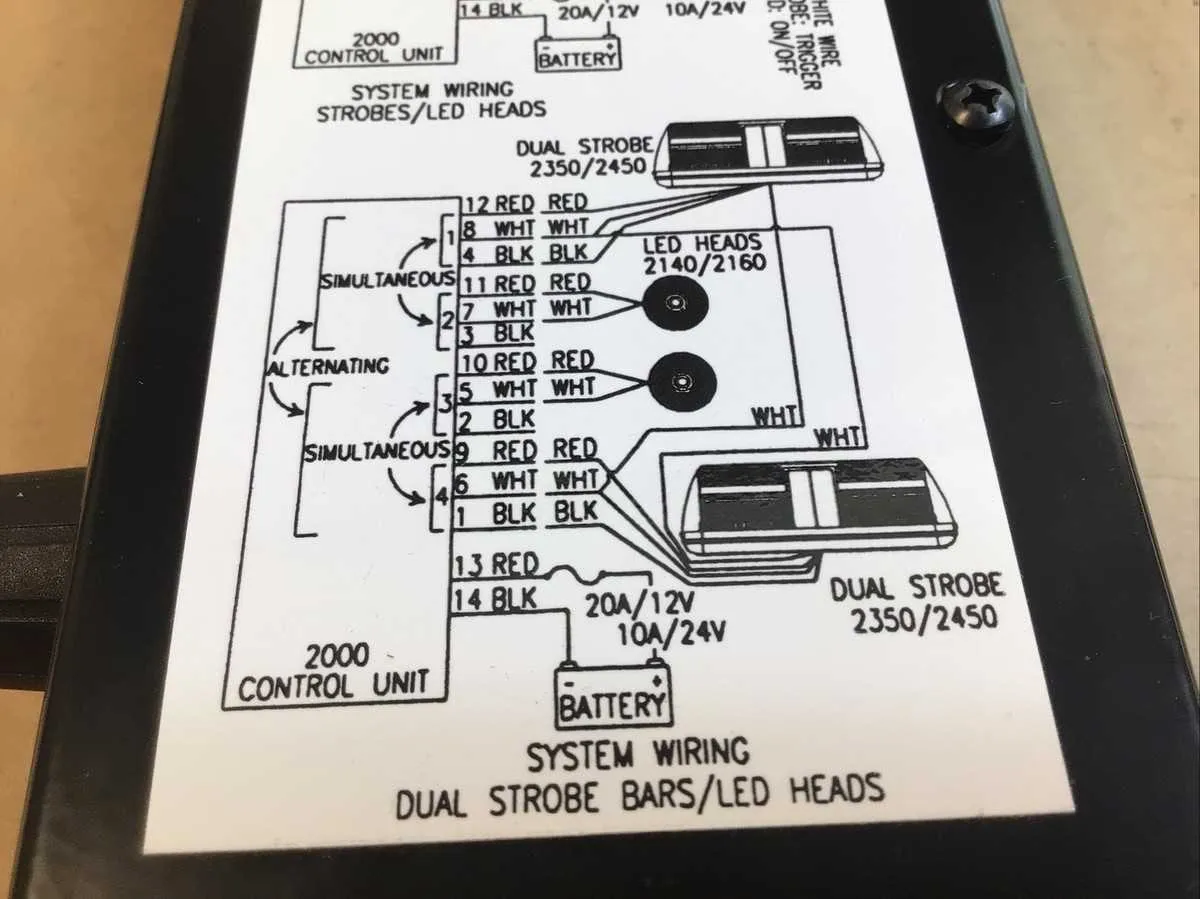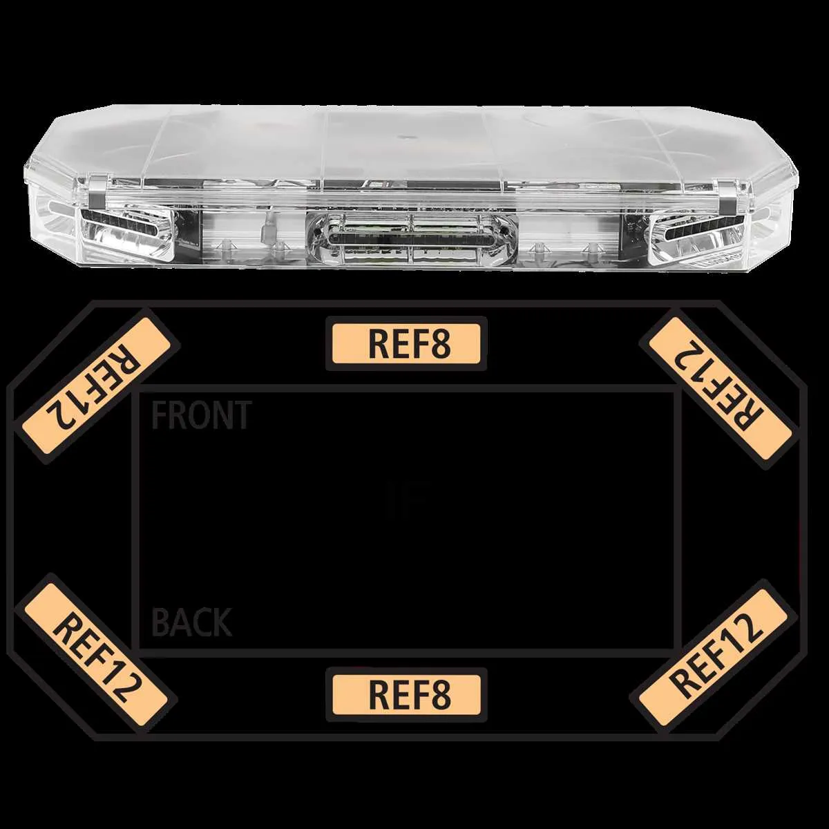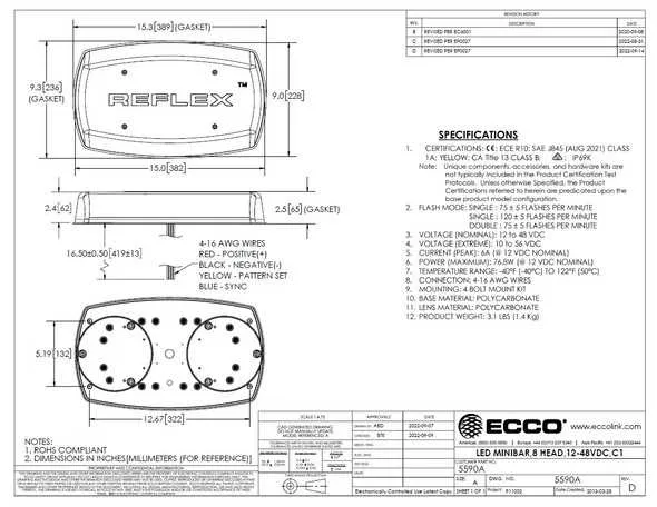
To ensure proper installation and functionality of your flashing warning device, first verify the correct wiring layout. Use the standard color code for your model to avoid confusion: typically, the power input will be connected to the red wire, while the ground will be linked to the black one. Always double-check that each connection is secure, and never rely solely on the manufacturer’s generic guide–consult the specific electrical blueprint for accurate terminal connections.
Next, pay close attention to the polarity of the system. Incorrect connections can lead to malfunction or permanent damage to the internal components. When linking to a control panel, connect the power output terminals carefully, following any provided sequence. Make sure to tighten any screw terminals to avoid loose connections, which can lead to unreliable operation.
Additionally, if the unit is designed with an integrated fuse or protection circuit, check the fuse rating to match the electrical load requirements of your setup. Under or over-rated fuses can cause unnecessary system interruptions. Lastly, confirm the compatibility of your device with existing power sources–an incompatible voltage can easily cause failure or erratic flashing patterns.
Wiring Guide for EZ00062 Model Flashing Signal Device
Ensure you connect the power cables correctly: the positive wire should be attached to the vehicle’s main power source, typically a 12V DC terminal, while the negative should be grounded to the chassis. Use high-quality connectors to prevent corrosion over time. For a secure connection, it is recommended to solder the wires and then insulate them with heat shrink tubing to protect against moisture ingress.
If you’re installing multiple units, make sure each device has a dedicated power line to avoid overload. Running wires in parallel is acceptable, but only if the total load does not exceed the recommended amperage. For optimal functionality, use a fuse rated appropriately for the total current draw of the system, placed as close to the power source as possible.
When setting up the control switch, ensure it is capable of handling the current required for activating the unit. A standard 20A switch is often sufficient for most installations. Wiring the switch to the positive lead allows for an easy activation process, but consider placing a relay between the switch and the device to reduce wear on the control switch over time.
For a smooth operation, test all connections thoroughly before sealing any wiring. Check for any signs of faulty connections, such as heating or sparks when the system is powered on. If you notice issues, recheck the ground and power connections to ensure they are both secure and clean.
Proper cable routing is essential to prevent damage from moving parts or harsh environments. Route the cables through secure channels and use cable ties to keep them organized and out of harm’s way. This will also prevent chafing and improve the longevity of the system.
How to Connect Power and Ground Wires

To correctly connect the power and ground wires, follow these steps:
- Identify the power wire, typically marked in red or labeled with a “+” sign.
- Locate the ground wire, usually black or marked with a “-” sign.
- Ensure the power source is switched off before beginning any connections to prevent electrical shock.
- Connect the power wire to the positive terminal of the power supply.
- Connect the ground wire to a solid, metal part of the vehicle or equipment to ensure a proper earth connection.
- Use an appropriate connector to secure the power wire to the power supply terminal and the ground wire to the grounding point. Ensure that the connection is tight and secure to prevent any loose wires.
After the connections are made, double-check to make sure there are no exposed wires that could cause short circuits. Test the system to ensure everything is working correctly.
Understanding the EZ00062 Circuit for Proper Installation
Ensure correct polarity when connecting the power supply to the unit. The red wire should be attached to the positive terminal, while the black wire connects to the ground. Always verify that the voltage matches the specifications outlined in the technical manual to avoid electrical malfunctions.
Use a reliable fuse rated according to the manufacturer’s recommendations to protect the system from short circuits or power surges. The fuse must be installed in line with the power feed to safeguard the unit from excessive current.
For the switch control, use a relay to prevent overloads on the primary wiring. The relay should be rated to handle the current draw of the unit. Connect the trigger wire from the switch to the relay’s input terminal, ensuring a stable on/off function when activated.
Mount the device securely on a flat surface, away from excessive vibration. Ensure proper grounding to minimize the risk of electrical interference, which could impact the performance of the unit. Also, double-check the torque specifications for mounting hardware to prevent loosening over time.
When testing the system, start by verifying the output sequence and timing. Perform a continuity check across all connections to ensure there are no faults before powering on the device. This will help confirm the unit is ready for use without risk of malfunction.
Troubleshooting Common Electrical Issues in the EZ00062 Flashing Signal System

Check for power supply interruptions first. A sudden failure in your system could indicate a loose connection or faulty power source. Ensure the fuse is intact and not blown. Replace it with the appropriate amperage rating if necessary.
Inspect the connections for any signs of corrosion or dirt buildup. Use a contact cleaner and secure all terminals properly to ensure smooth conductivity. Weak connections are a common cause of intermittent operation.
If the unit is not activating, verify the control switch is functional. Test the switch with a multimeter to confirm it’s sending the correct signal. If it’s malfunctioning, replace the switch to restore full functionality.
Examine the ground wire for any breaks or loose connections. A poor ground can prevent the unit from working at full capacity or cause erratic behavior. Clean and reattach the ground securely to a metal surface.
For systems with multiple flashing modes, ensure that the mode selector is set properly. A misconfigured setting can cause the unit to malfunction or fail to initiate correctly.
If the flashing pattern is inconsistent, check the relay responsible for switching modes. A damaged or worn-out relay may need replacing to correct irregularities in the light sequence.
Lastly, assess the unit’s internal circuitry for any visible damage or burnt components. In case of internal failure, contact a professional technician for repair or replacement of the defective parts.