If you’re planning to control a single light from two different locations, the setup requires a specific connection arrangement that ensures proper functionality. This type of system typically involves two controlling devices that work together to turn the light on or off from either point.
Understanding the connections is critical for achieving the desired result without risking faults. In this case, two separate controllers are involved, where the first one sends the signal to the second. The second device responds by completing the circuit, either turning the light on or off based on the initial input.
Correct terminal placement is essential. Each controller has designated terminals for connecting the power source, the fixture, and the traveler wires. Proper placement and secure connections at these points are crucial for the system to operate smoothly and safely.
Ensure that the neutral wire is never switched, as this can lead to dangerous electrical issues. A common mistake is reversing the live and neutral conductors, which can cause short circuits or even potential fire hazards. Verify all connections before powering the circuit.
3-Way Control System for Lighting
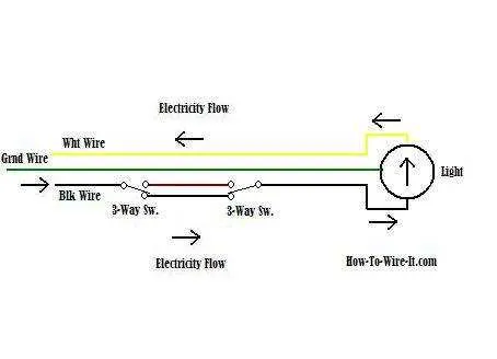
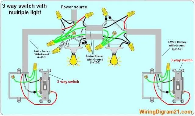
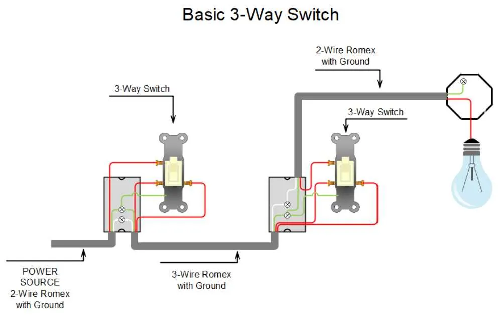
For optimal installation of a dual-location lighting control setup, ensure both devices are connected to the same power source and use two traveler wires for interconnection. The first unit should have the common terminal linked to the incoming live wire, while the second device must connect to the load (light fixture). One of the traveler terminals on each device will be used for a wire that links them directly, and the second traveler terminal must connect to the opposite terminal on the second unit.
When configuring the two devices, the key is to ensure that the common terminal of the first device is always tied to the incoming live wire, while the common terminal of the second device connects to the fixture’s live input. The other terminals are for traveler connections between the devices, ensuring control from both points in the room.
Ensure the neutral wire runs directly from the fixture to the power source, and avoid connecting it to either of the control units. Proper grounding is crucial to ensure safety in the system. Double-check the wire placement to prevent any errors that could result in malfunction or safety hazards. This arrangement allows you to control the fixture from two locations effectively and reliably.
How to Connect a 3-Wire Device for Single-Pole Use

To wire a 3-wire device for a single-pole application, ensure the power source is disconnected before starting. Begin by identifying the common terminal, which will connect to the power supply. The other terminals will connect to the two traveler wires, which control the flow of current between the device and the light fixture.
Connect the black (hot) wire from the power source to the common terminal. The red and black wires (travelers) will connect to the remaining terminals. These wires should be correctly identified and matched, as they determine the path of current under different conditions.
Next, connect the neutral wire from the power source directly to the light fixture. Ensure that all connections are securely tightened and no wires are exposed. Finally, test the setup by turning the power back on, ensuring the device correctly controls the light fixture as expected.
Common Mistakes When Connecting a Dual-Control Circuit and How to Avoid Them

Improper connections are the most common issue when setting up a dual-control electrical system. Follow these guidelines to prevent errors:
- Ensure the power source is correctly linked to the common terminal on the first control device. Incorrect connections can lead to malfunctions.
- Double-check that travelers are properly connected to the terminals. Misplacement often results in intermittent operation or no function at all.
- Don’t reverse the terminals for the hot wire and neutral. This mistake can cause safety hazards and malfunctioning.
- Ensure that both devices are correctly grounded. Missing or poor grounding can lead to electrical shocks or fire risks.
- When connecting the traveler wires, always use the same color coding for consistency across both controllers. This will avoid confusion and reduce errors.
By following these guidelines, you will ensure a more reliable and safer installation process.
Step-by-Step Guide for Connecting the Traveler Wires in a 3-Way Setup
Start by identifying the common terminal on the first device. This is the point where the power supply enters. The traveler terminals are usually located next to the common terminal and should be marked accordingly on the device. In your setup, you will connect one traveler wire to each of these terminals.
Step 1: Prepare the traveler wires by stripping about 1/2 inch of insulation from each end. This will ensure a solid connection to the terminals.
Step 2: Insert one traveler wire into the first device’s traveler terminal. Tighten the screw securely to hold the wire in place. Repeat this step on the second device by connecting the second traveler wire to its corresponding terminal.
Step 3: Ensure that both traveler wires are connected to the correct terminals. Double-check the connections to avoid incorrect wiring. The wire coming from the power source should go to the common terminal, while the travelers connect to their respective terminals.
Step 4: After securing both wires, test the connections by turning the power back on and verifying that the lights function correctly when toggling the devices.
Note: If the lights do not respond as expected, recheck the traveler wire connections to ensure they are placed on the correct terminals, and no loose connections exist.