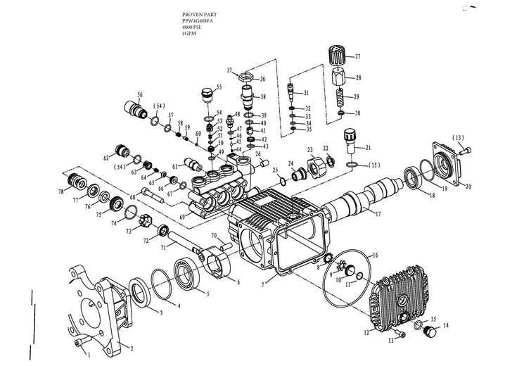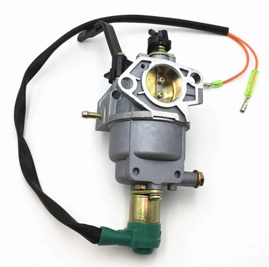
Recommended Component Breakdown
For immediate reference, the valve assembly should be inspected first. Pay close attention to rocker arms, valve springs, retainers, and cotters. Ensure no wear or deformation; replace as needed using original equipment manufacturer (OEM) items to maintain performance.
Key Assemblies and Element Listings

- Carburetor Section: Includes float chamber, jets, throttle shaft, and gaskets. Always confirm gasket fitment before installation to avoid air leaks.
- Ignition Assembly: Comprises coil, flywheel, and spark plug. Maintain proper gap on the plug (usually 0.7–0.8 mm) for optimal ignition.
- Recoil Starter: Check rope, pulley, and recoil spring. Lubricate lightly to prevent sticking; avoid over-oiling.
- Fuel System: Contains fuel tank, cap, filter, and petcock. Regularly clean the filter and check petcock function to prevent blockages.
Maintenance-Focused Details
- Crankcase Area: Includes crankshaft, connecting rod, and piston assembly. Confirm torque settings on connecting rod bolts (usually 12–14 N·m) to avoid internal damage.
- Cooling Mechanism: Encompasses fan cover, flywheel fins, and shrouds. Remove debris regularly; blocked airflow leads to overheating.
- Governor Mechanism: Contains governor arm, springs, and spool. Ensure spring tension matches factory specification; incorrect tension causes unstable RPMs.
For precise alignment, refer to OEM reference numbers stamped on each element. Avoid mixing non-OEM substitutes, as slight dimensional differences can affect overall engine function. Always tighten fasteners following a crisscross pattern to distribute load evenly, particularly on cylinder head and intake sections.