Ensure proper connection of all three components to guarantee smooth operation of the electrical generation system. The key to success lies in proper identification and correct wiring of the charging unit’s terminals. A failure to do so can result in inefficient energy production, potentially leading to a system malfunction. Verify each connection point before proceeding with installation.
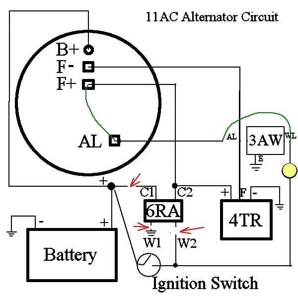
The first lead typically connects to the power supply and acts as a main feed. It plays a critical role in ensuring stable voltage flow. The second lead should be securely linked to the output terminal, providing a steady stream of energy to the required components. Finally, the third lead is crucial for regulating the system’s overall performance by maintaining correct voltage levels.
When troubleshooting or upgrading, pay particular attention to the resistance levels at each junction. Even slight miswiring can cause discrepancies in output. Proper maintenance and periodic checks ensure optimal performance and prevent unexpected failures.
Understanding the Three-Terminal Charging System

To ensure optimal performance of the electrical system, follow these key steps when configuring a three-terminal charging unit:
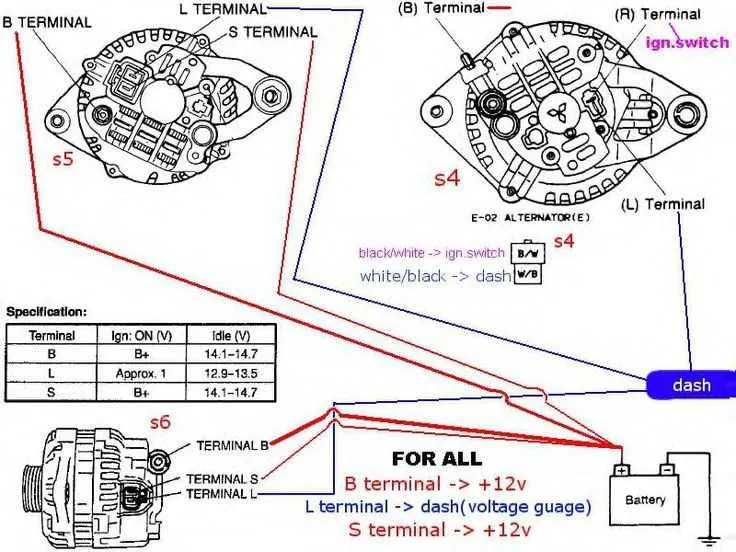
- Terminal 1: Battery Connection – This is the primary terminal responsible for power input. It must be securely connected to the battery’s positive terminal to supply the necessary charge to the storage unit.
- Terminal 2: Ground Connection – Proper grounding is essential. Attach the second terminal to a reliable chassis ground to complete the circuit and prevent electrical faults.
- Terminal 3: Sensing Connection – The third terminal regulates voltage output. Link this terminal to the voltage regulator or control unit for real-time monitoring of the charging system’s performance.
Follow these steps for correct installation:
- Start by securing the battery terminal for a stable power flow.
- Ensure that the ground connection is free from corrosion and securely fastened.
- Finally, connect the sensing terminal to the appropriate voltage control unit.
For long-term reliability, inspect all terminals periodically for corrosion or wear, and clean or replace connections as necessary.
Understanding the Key Components in a 3 Wire Charging System

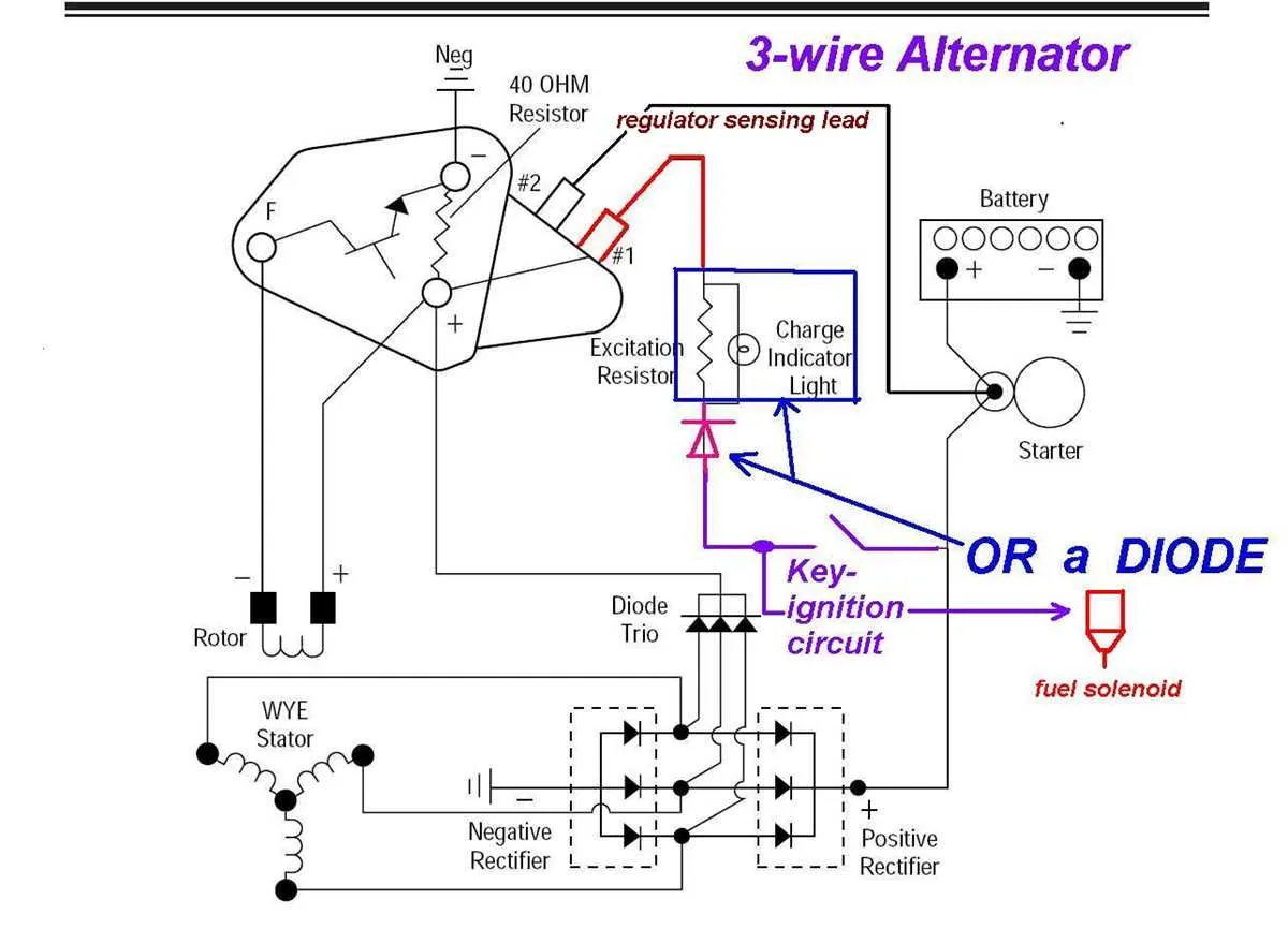
The system involves three essential parts: the regulator, the stator, and the excitation circuit. The regulator manages voltage levels by adjusting the current sent to the excitation component. This helps to maintain a stable voltage output, which is critical for charging the battery and powering electrical systems.
The stator, consisting of coils, generates alternating current (AC) when the rotor turns. This AC is then converted into direct current (DC) by the rectifier, which is crucial for battery charging. A solid connection between the stator and regulator ensures that the correct amount of energy is generated and used efficiently.
The excitation circuit controls the strength of the magnetic field produced by the rotor. This magnetic field is what drives the stator to generate electrical energy. Proper regulation of this circuit is necessary to prevent overcharging or undercharging the battery, which could lead to system malfunctions.
Wiring and Connections for Proper Functionality
Ensure the correct routing of the power source to the regulator for consistent voltage output. Begin by connecting the positive terminal to the battery. This connection is critical to ensure that energy flows smoothly from the power unit to the system.
Next, establish a solid connection between the ground terminal and the engine block or vehicle chassis. This step completes the circuit and allows for proper dissipation of any electrical surge or excess energy.
Finally, the signal wire should link directly to the control module to ensure optimal performance. The connection must be secure to avoid signal interruptions. Improper connections here may lead to fluctuating power output or erratic behavior in the system.
Troubleshooting Common Issues with 3 Terminal Charging Systems
If you’re experiencing charging problems, start by checking the voltage output. A properly functioning unit should generate between 13.8V and 14.4V at idle speed. If the reading is below 13V, inspect the connection to the voltage regulator and ensure that it’s securely attached. A loose or corroded connector could be causing the issue.
Next, verify the continuity of the primary input. If the device is not charging the battery, ensure that the lead from the battery to the charging component is intact and free from damage. Look for signs of wear or fraying, which could lead to poor contact or a complete failure in power transfer.
If you’re facing irregular voltage fluctuations, examine the ground connection. A weak or poor ground can result in unstable performance, affecting the entire system’s ability to maintain consistent charging. Check for any corrosion at the grounding point and ensure it’s securely fastened.
For excessive noise or surges, investigate the regulator. Faulty regulators can cause erratic voltage output. To test, measure the voltage at varying engine speeds. A fluctuating output suggests that the regulator might need replacing or recalibrating.
Lastly, if the system fails to start charging after all connections appear solid, inspect the internal components for any signs of wear or damage. Damaged diodes or an ineffective brush can cause the charging mechanism to malfunction completely, requiring a deeper inspection or a component replacement.