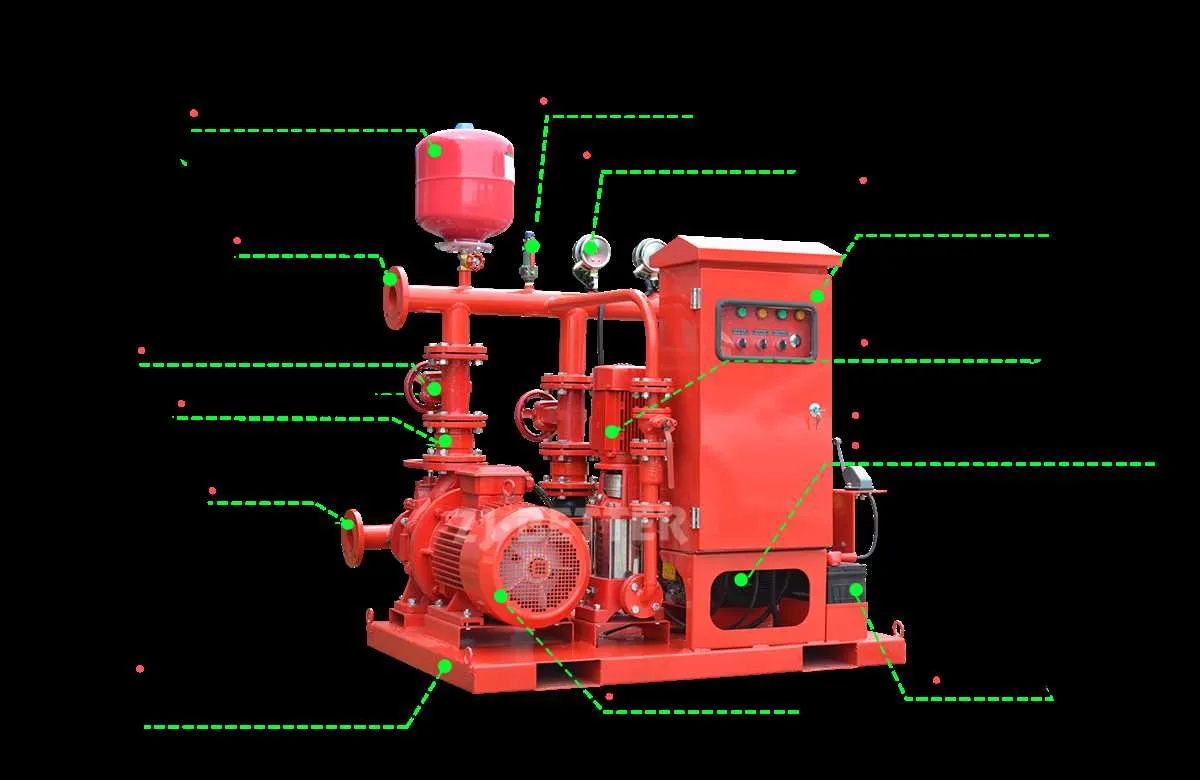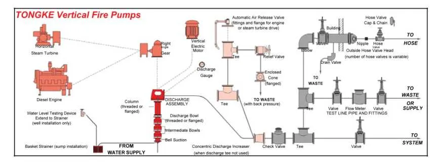
Ensure optimal performance by maintaining a reliable auxiliary water source setup. Proper configuration and coordination between various water delivery components are crucial to providing adequate pressure and flow for critical systems in case of emergencies.
The main engine should be regularly monitored to guarantee that it operates within its design parameters. Keep an eye on the motorized unit as its task is to maintain pressure within the pipeline during initial stages and throughout the system’s operation.
It’s important to use the control system efficiently to monitor flow rate, pressure levels, and ensure that all components are synchronized. Failure to adjust these parameters might lead to system inefficiencies or failure under high-demand scenarios.
Regular maintenance is essential for long-term operation. Check for leaks, wear and tear on seals, and examine the condition of rotating elements that help deliver water to various parts of the facility.
System Overview and Operation of Auxiliary Pressurization Units
Ensure the auxiliary pressurization unit is correctly sized for the system’s flow requirements, maintaining sufficient pressure for automatic activation. The primary component responsible for maintaining pressure when the main units are idle is the small auxiliary unit, which automatically engages when pressure drops below a predefined level.
Key Components: The system incorporates a motor-driven unit to maintain constant pressure in the pipeline, especially during low demand. A small capacity unit should be employed for this purpose, designed to meet operational needs without overloading the system. It is essential to avoid oversized units that could lead to inefficiency and increased energy consumption.
Operation Protocol: The auxiliary unit engages once the pressure dips, delivering just enough water flow to restore system pressure to its optimal level. The system should feature reliable pressure sensing mechanisms and control panels that activate the auxiliary unit seamlessly. Ensure that the unit is integrated with the control systems to provide timely alerts in case of malfunction.
Maintenance Considerations: Regular inspection and maintenance of the smaller unit are crucial. Check for any wear on seals, bearings, and valves. Lubrication of moving parts should follow manufacturer specifications. Verify that sensors are calibrated to avoid false activations or failures.
Efficiency Maximization: To enhance operational efficiency, install variable speed drives where applicable. This allows the smaller unit to adjust speed according to demand, reducing energy consumption and extending the service life of the components.
Detailed Wiring Schematics for Pump Systems

Ensure all connections follow the manufacturer’s wiring guidelines to prevent errors in the electrical layout. Power sources should be routed to the control panel, where both automatic and manual start circuits are incorporated. Pay attention to the grounding of the system, ensuring a direct path to the main electrical ground to avoid potential electrical hazards.
For control systems, use reliable relays and sensors to monitor motor performance. The main relay should be configured to trigger activation when low-pressure or other operational conditions are detected. Include isolation switches for safety during maintenance procedures.
Incorporate overload protection devices for each motor, ensuring they can be reset manually. Double-check the motor wiring to ensure that the phase connections match correctly. Phase rotation indicators should be installed to detect any miswiring that could cause operational issues.
Wires connected to the system must be rated for the expected load and climate conditions. Use heat-resistant cables where applicable and ensure connectors are properly insulated to prevent short circuits. Ensure that emergency stop buttons are clearly visible and accessible in case of system malfunction.
For remote monitoring, integrate data collection points that can send operational statistics to centralized systems for analysis. Connect any auxiliary sensors that monitor pressure or flow rates to the main control panel. This will allow real-time system status to be displayed on an HMI screen.
Finally, ensure that the entire system is thoroughly tested according to national and international electrical standards before becoming operational. Perform a series of live tests to confirm correct circuit behavior under various fault conditions.
Jockey Pump Integration with Fire Protection Systems

Always configure the pressure maintenance unit to operate independently from the primary suppression assemblies. This ensures system readiness without frequent activation of main equipment.
- Set the activation threshold 10–20 psi below the main device’s start point to maintain line pressure effectively.
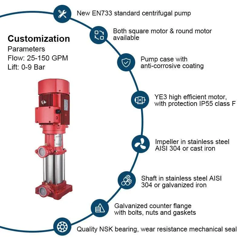
- Use a vertical multistage centrifugal model for consistent flow and compact footprint in mechanical rooms.
- Incorporate a pressure switch with ±1 psi differential for precise cut-in and cut-out settings.
- Install a check valve immediately downstream to prevent reverse flow and pressure fluctuations.
- Integrate a manual bypass loop for maintenance without system shutdown.
When sizing the auxiliary booster, limit flow capacity to 1%–3% of the primary deluge unit to avoid unintended trigger events. Use stainless steel piping and fittings to reduce corrosion risk in high-humidity environments.
- Calculate system static and residual pressure precisely.
- Select a motor with a minimum service factor of 1.15 for reliability.
- Test monthly under no-flow conditions to verify pressure retention capability.
Ensure compatibility with the control panel’s logic to prevent false alarms and coordinate shutdown sequences. Include a surge suppressor on the power circuit to mitigate damage from voltage spikes.
Troubleshooting Common Issues in Turbine and Jockey Pump Systems
Verify suction pressure first: inadequate inlet pressure often leads to cavitation, resulting in excessive vibration and impeller damage. Check the supply line for blockages or closed isolation valves.
Monitor discharge flow: if output is lower than expected, inspect for clogged strainers, partially closed discharge valves, or worn wear rings. Measure differential pressure across the system to locate restrictions.
Examine control panel signals: unexpected starts and stops typically originate from faulty pressure switches or sensor calibration drift. Confirm setpoints against system requirements and replace damaged wiring or connectors.
Inspect shaft alignment regularly: misalignment causes bearing wear and seal failures. Use dial indicators or laser tools to ensure concentricity between driver and driven components.
Check auxiliary device cycling frequency: excessive starts may indicate a leak in the downstream piping or incorrect pressure band settings. Verify pressure drop rates and recalibrate controllers accordingly.
Listen for unusual noises: high-pitched whines or grinding sounds often signal bearing degradation or foreign object ingestion. Perform vibration analysis and disassemble if necessary to prevent further damage.
Confirm motor performance: elevated amp draw could indicate mechanical binding or internal obstruction. Compare current readings with nameplate values and inspect for rotor imbalance or bent shafts.