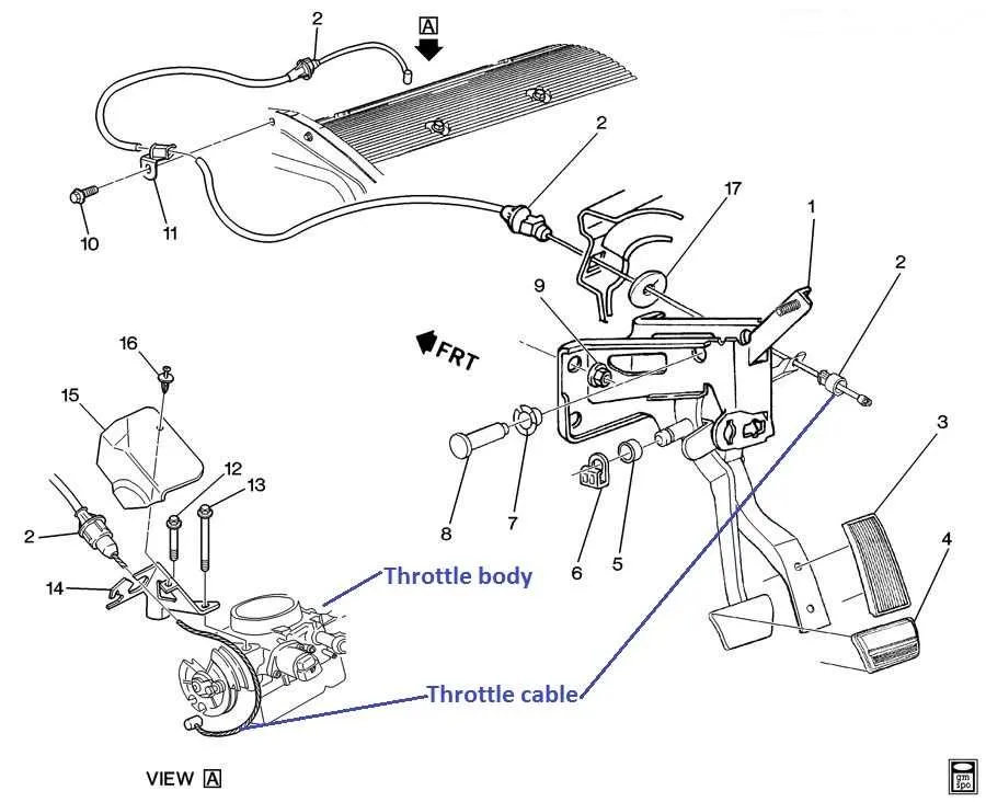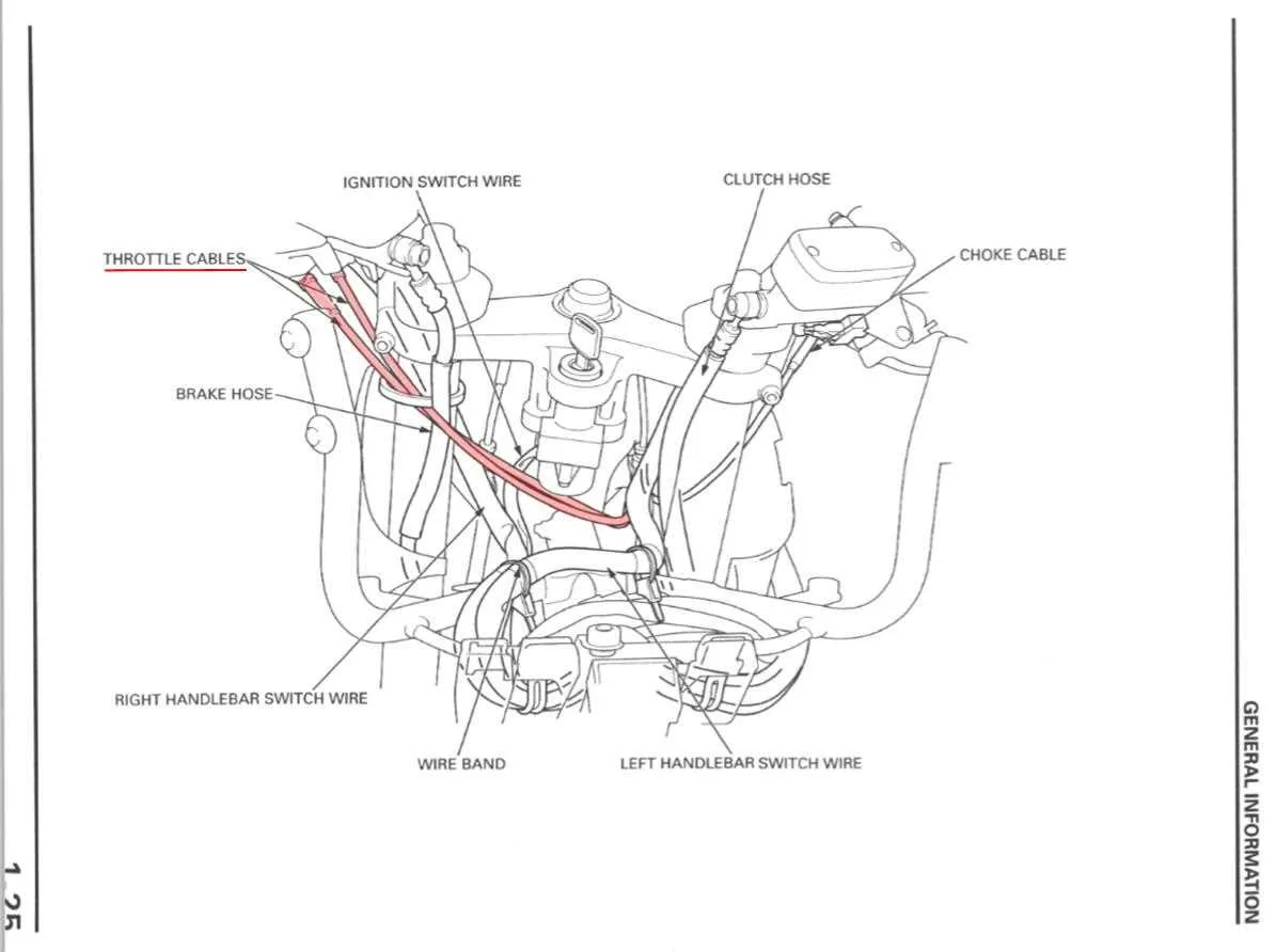
For proper engine performance, it’s crucial to understand how the mechanism controlling airflow functions. Ensuring accurate adjustments in the connection between the pedal and intake valve can prevent irregularities in the engine’s response. An important step in diagnosing or replacing components involves checking the linkages and their routing through the engine compartment.
Inspect the components carefully–pay close attention to the pulley system, the position sensors, and the physical connectors. Regular maintenance can avoid unnecessary wear on these parts, which could lead to poor throttle control or engine hesitation. An incorrect setup can result in throttle sticking or erratic RPM changes, often caused by improper cable routing or excessive slack.
When reassembling or replacing any part of this system, ensure the routing matches the manufacturer’s specifications. Position sensors and adjustment points should be calibrated accurately to guarantee smooth operation. If components like the actuator or linkage parts show any sign of wear, immediate replacement is advised to maintain optimal performance.
Understanding the Linkage and Control Mechanism
Ensure proper alignment of the control linkage to guarantee smooth airflow regulation. The component that connects the accelerator pedal to the intake valve should be checked for tension and any signs of wear. A damaged or incorrectly adjusted system will result in unresponsive acceleration or inconsistent engine performance.
Pay close attention to the routing of the connection, making sure there are no obstructions or fraying. The path must be clear, and the cable should have sufficient slack to allow for full pedal movement. If the component is not returning to its resting position, it may need lubrication or replacement to restore functionality.
Examine the linkage for any signs of corrosion or misalignment. Over time, the parts may degrade, causing resistance that interferes with the smooth operation. Replacing old or worn components is crucial to avoid power loss and to ensure optimal engine performance.
Check the tension on the mechanism at various throttle positions. It should feel consistent without any stiffness or play. If the response is delayed or irregular, consider recalibrating or replacing the control elements. Proper tension is critical for responsive driving and maintaining fuel efficiency.
Finally, always test the system after maintenance to confirm that the connection operates without any hindrance. This step ensures that the vehicle’s power delivery remains efficient and responsive across different speeds.
Understanding the Components of a Throttle Body Cable System
The primary parts of a control linkage system include the control lever, the linkage mechanism, and the actuator. The control lever, typically located in the vehicle’s cabin, is used by the driver to modulate the airflow into the engine. The linkage connects the control lever to the actuator, which adjusts the intake valve or similar component to regulate engine performance.
Inspect the actuator for any signs of wear or misalignment, as this part directly influences engine response. Over time, the internal springs or electronic components of the actuator may lose functionality, leading to poor acceleration or inconsistent engine behavior.
The intermediate linkage, often consisting of metal rods or flexible connections, transmits the driver’s input to the actuator. Ensure these components remain free of kinks or excessive slack, as this could reduce response time or cause delays in engine performance adjustments.
Regular lubrication and inspection of the moving parts in this system will prevent premature wear. Keep an eye on the connection points to ensure they are properly secured, as loose components can lead to erratic engine behavior or potential failure of the system.
How to Identify Common Issues with the Accelerator Linkage

Check for signs of wear and tear on the accelerator mechanism. If you experience delayed acceleration or erratic response when pressing the pedal, the linkage may be sticking or have become misaligned. Inspect the connections for any fraying, corrosion, or dirt accumulation, as these can cause friction and affect smooth movement.
Another common issue is a loose or overly tight connection. A loose linkage might cause inconsistent pedal feel, while a tight one can make the pedal hard to press. Verify the proper tension by checking for resistance when moving the linkage manually. If there’s too much force required, it might need lubrication or adjustment.
Also, listen for abnormal sounds such as grinding or squeaking, which can indicate parts rubbing against each other due to lack of lubrication or misalignment. Addressing these sounds early can prevent further damage.
If the vehicle has difficulty returning to idle speed after accelerating, it may point to an issue with the spring mechanism or a blockage in the linkage pathway. Clean any obstructed parts and ensure that the spring mechanism is intact and functioning properly.
Lastly, observe any unusual pedal behavior like sticking or irregular movement. This can be a sign of an obstruction in the mechanism or a misaligned component. Regular inspection and proper maintenance can prevent these problems from becoming more serious.
Step-by-Step Guide to Replacing a Throttle Control Linkage
Start by ensuring the vehicle is off and the ignition key is removed. Engage the parking brake to prevent movement.
- Locate the control mechanism at the intake manifold. Inspect the connection points to ensure they are visible and accessible.
- Use pliers to detach the retaining clip securing the wire to the linkage. Take note of its placement for reinstallation.
- Follow the wire path to the pedal area, disconnecting it from its anchoring points. Mark any specific routing or alignment to ensure proper placement of the new part.
- Remove any fasteners or covers that may obstruct access to the adjustment bolts or the mounting area.
- Once the old part is fully detached, compare it with the new replacement. Ensure both parts match in length, connection points, and other specifications.
- Position the new component in place, securing it first at the pedal assembly and then at the intake. Be mindful of any adjustments needed to ensure smooth movement.
- Reattach any fasteners or clips removed during the process, checking for proper alignment.
- Test the replacement by manually adjusting the linkage, ensuring there is no excessive slack or tension. The movement should be fluid and responsive.
- Start the engine and check for any abnormalities in the throttle response. Ensure the new linkage is functioning correctly at various throttle positions.
- Finally, reassemble any covers or panels removed during the process and clean the working area.