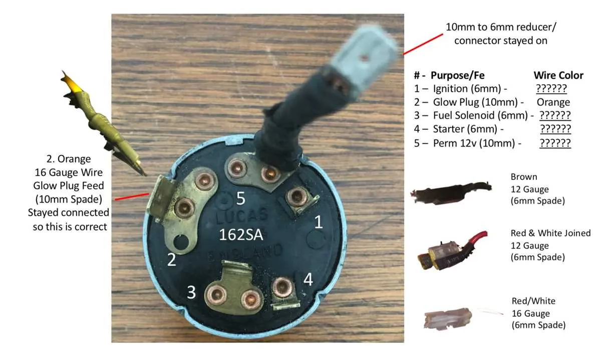
Connect the red lead to a constant 12V source; this typically links directly to the battery. Ensure the contact is clean and corrosion-free to avoid voltage drops.
The black output feeds the starter solenoid. Activate this channel only when turning the key to the start position. Use a multimeter to verify continuity when the tumbler is fully rotated forward.
Brown or yellow routes power to essential systems during the “on” position. This path energizes the fuel system, relays, and other accessories. Confirm stable voltage using diagnostic tools before securing the connector.
The green path usually corresponds to the accessory position. This contact powers non-critical components like radio or dashboard lighting. Ensure this segment only receives current when the control key is in the appropriate detent.
Note: Always label each conductor before disassembly and double-check pin positions using a factory reference. Incorrect placement may result in short circuits or non-functioning systems.
4 Wire Ignition Switch Diagram
Connect the power input to a fused 12V source directly from the battery. Use a red conductor with appropriate insulation rating for automotive applications.
Route the accessory lead to devices like the radio or fan relay. This output typically becomes active in the second turn position. Confirm voltage output with a multimeter during key cycling.
Link the starter trigger to the solenoid terminal on the cranking system. This path should only energize during the start position and must be tested for continuity only in that mode.
Attach the run output to engine control components, such as coils or electronic modules. Ensure that this line holds steady voltage during both the run and start positions.
Label all lines with shrink tubing or tags before finalizing connections to avoid miswiring during installation or future diagnostics.
Identifying Wire Functions in a 4-Wire Setup
Begin by using a multimeter to test continuity and voltage. Label each lead after verification to avoid misconnection. Follow this sequence for precise identification:
- Power Input (B+): Usually red. Delivers constant 12V from the battery. Confirm with voltage test–should show 12V regardless of key position.
- Starter Signal: Typically yellow or purple. Receives 12V only when the key is turned to start. Test by probing during crank position.
- Accessory Feed: Often brown. Supplies power to non-essential components like radio when in the ‘ON’ position. Verify by turning to ‘ON’ without starting.
- Main Output (Run/ON): Usually black or pink. Provides voltage to essential systems (e.g., ignition coil, ECU) when in ‘ON’ and ‘START’. Confirm by checking power during both positions.
Use heat-shrink labels or permanent markers to tag each line post-verification. Avoid guessing based on color alone–always validate with a test tool.
How to Connect a 4-Wire Ignition Switch Safely

Start by disconnecting the vehicle’s battery to prevent short circuits or accidental activation. Identify the four conductors: power input, starter trigger, accessory circuit, and run output. Use a multimeter to verify each terminal’s role before proceeding.
Secure the power input to the 12V source from the fuse box or starter solenoid. Ensure the connection is protected by an inline fuse rated for the circuit’s load, typically 20-30 amps. Route the run output to the engine management relay or coil system. Confirm continuity and voltage stability under load conditions.
Attach the starter trigger to the solenoid’s control terminal using a dedicated path to prevent voltage drop. Use crimp connectors with heat-shrink tubing for all joints to maintain insulation integrity. Lastly, link the accessory terminal to circuits such as HVAC or radio, ensuring it only energizes in the ON position.
After all links are established, reconnect the battery and test each function individually: crank, accessory mode, and engine operation. Check for voltage spikes, loose terminals, or unintended current draw. If anomalies occur, isolate and correct immediately to avoid system failure or fire risk.
Troubleshooting Common 4-Wire Ignition Switch Issues
Begin by verifying voltage at the primary input terminal using a multimeter set to DC mode. Ensure a consistent 12V is present when the key is in the ON position. No reading indicates a break in the power feed or a faulty fuse.
Next, test continuity between the accessory contact and the load terminal. With the key turned to ACC, resistance should be near zero. Any significant resistance suggests internal corrosion or worn-out contacts.
Inspect the start position circuit by checking for output signal when the key is turned to START. If voltage is missing, examine the connection to the starter relay and ensure it activates properly. A silent relay may mean coil failure or insufficient grounding.
Evaluate the ground connection integrity by checking for a solid path between the housing and chassis. High resistance here can cause intermittent behavior, especially under vibration.
Finally, disconnect the harness and visually inspect terminal condition. Signs of heat discoloration, deformation, or loose crimping point to poor contact quality, which may require connector replacement or re-termination.