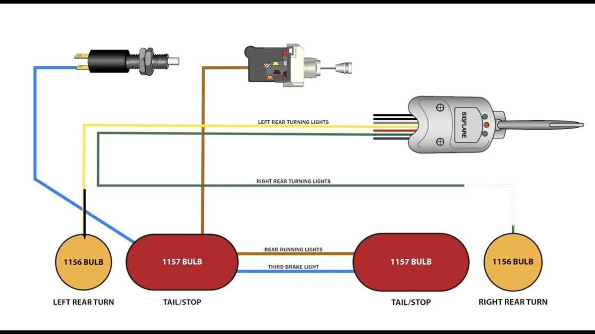
For optimal performance of the rear illumination and indicator system in your vehicle, ensure a proper connection using only three conductors. This method simplifies the setup while maintaining functionality. By correctly identifying each terminal’s role, you will prevent electrical shorts and interference between distinct systems.
Begin by isolating the conductor dedicated to rear illumination. This should be connected to the appropriate source, ensuring it receives a consistent voltage supply for when the vehicle is in operation. The next step involves identifying the circuit that activates the indicator mechanism, which needs to be linked to the system that engages when a change in direction is requested. Finally, the third conductor plays a key role in activating the brake response, triggering a sudden increase in illumination when applied.
Note that these conductors must be securely insulated to avoid unwanted contact or signal disruption. A simple but efficient method is to use specialized connectors or crimps designed for these systems, offering reliable and long-lasting results.
By following these steps precisely, you will enhance both safety and visibility, ensuring compliance with regulations and improving the driving experience.
3-Wire Electrical Setup for Indicator and Stopping System

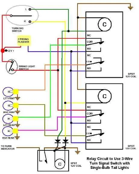
For a 3-conductor system that controls both the stop function and the indicator, the key is ensuring the correct connections for proper operation. The system typically uses one conductor for the power supply, one for activation by the foot mechanism, and one for the indicator function.
First, connect the first conductor to the positive terminal of the battery. This ensures a stable flow of energy to the whole system. The second conductor should be routed through the actuator, so it gets activated when the pedal is pressed. The third conductor needs to go through the mechanism that activates the indicator lights, and should be connected to the separate circuit responsible for the signaling system.
It’s important that all connections are secure and insulated to avoid any shorts. Double-check the connections after installation to ensure no cross-talk between the functions. The third conductor should be carefully routed, keeping in mind that it should only interact with the indicator portion when required.
To finalize the setup, test the system by engaging each function separately. When the foot mechanism is activated, it should trigger the first function. Similarly, activating the indicator system should not interfere with the first function. Both functions should operate independently but share a common conductor, allowing them to coexist efficiently.
Understanding the 3-Wire System for Brake and Turn Signals
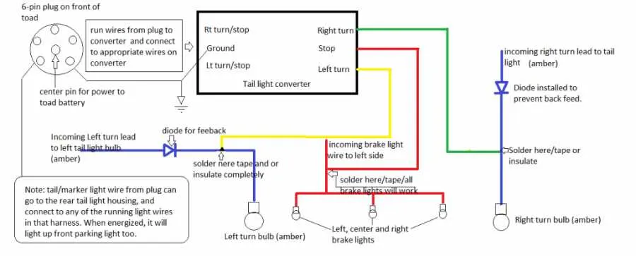
When working with a 3-wire setup for indicator functions, it is essential to know the role each connection plays in the overall system. Here is a breakdown of the wiring used to control both the stop function and the indicator lights.
- Common Ground: One of the connections in the system serves as the shared return path. This is crucial for completing the circuit and ensuring proper functionality across both the stop and indicator lights.
- Dedicated Function Lines: The remaining two wires are responsible for distinct actions. One is dedicated to activating the indicator function, while the other controls the stop function.
- Power Input: The power supply typically comes from the vehicle’s electrical system, and it’s necessary to ensure that both functions receive proper voltage to perform correctly.
Correctly identifying which wire corresponds to each function is vital for troubleshooting. Start by confirming the ground connection and proceed with checking the other two for voltage using a multimeter. One will show voltage when the brake pedal is pressed, and the other will fluctuate when the indicator is activated.
- Color Coding: Many setups use color coding to differentiate these functions. The color for the stop wire is commonly red or black, while the indicator may be yellow or green. However, always refer to your specific system documentation.
- Testing: After confirming proper connections, test each function separately. Ensure that activating the indicator does not affect the operation of the stop function and vice versa.
Maintaining proper insulation and avoiding short circuits is essential for safety. Ensure each wire is securely connected to the corresponding terminal, and double-check the integrity of the insulation before powering on the system.
Step-by-Step Guide to Installing a 3-Wire Setup for Indicators
1. Prepare Your Components: Ensure you have the necessary parts: a three-conductor setup, connectors, and a switch to control the circuits. Also, check that you have access to a power source and ground points for the system to function properly.
2. Connect the First Conductor: The initial connection is typically for the main circuit, often linked directly to the power source. Attach this line securely to the terminal designated for the main function. Make sure to confirm the polarity to avoid short circuits.
3. Secure the Second Conductor: This is usually the line that engages when the system needs to indicate a change in position. It should be routed to the switch or mechanism that will activate it. Ensure a solid, non-interfering path to avoid signal loss.
4. Integrate the Third Conductor: This connection is often tied to the alternate function of the system. Route this conductor carefully to the correct activation point, ensuring it operates independently from the other circuits when needed.
5. Test All Functions: Before finalizing the setup, ensure that each function responds accurately to the switch. Perform a full check to confirm all actions trigger as expected. Adjust any connections as needed if the desired response isn’t achieved.
6. Finalize and Insulate: Once confirmed, secure all components in place. Use insulation or casing to protect exposed parts from weathering or damage. Ensure that each connection is firmly attached and sealed to prevent accidental disconnections.
Troubleshooting Common Issues in 3-Wire Brake and Turn Signal Wiring

Check for continuity first if your system isn’t functioning properly. A multimeter can help identify breaks in the connection or areas where the current isn’t flowing. Test each component individually before you move on to complex repairs.
If one side of the system isn’t activating, inspect the grounding connections. A poor ground can lead to inconsistent behavior or a complete failure of one side. Clean and reattach any corroded or loose grounding points.
Ensure the relays are working. If a relay is stuck in the open or closed position, it can cause the lights to remain on or not turn on at all. A simple test of the relay’s functionality using a multimeter can save time and frustration.
For flickering lights or weak illumination, inspect the connectors for corrosion or oxidation. These can cause poor contact, leading to inconsistent operation. A contact cleaner can resolve most of these issues.
Verify that each circuit has the correct voltage at the switch and the component ends. Low voltage could indicate a power supply issue or a faulty component in the circuit, which will need to be replaced.
If everything else seems fine but there’s still no response, test the component at its input and output. Sometimes the component itself is defective, even if all connections appear correct.
Lastly, check for any short circuits. Inspect all areas where wires may be rubbing against metal surfaces or each other. Shorts can quickly disrupt the flow of current, causing lights to malfunction or stay off entirely.