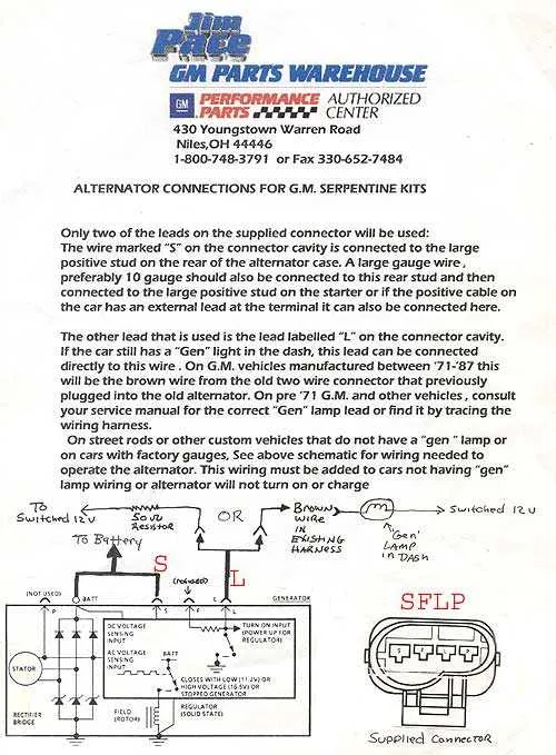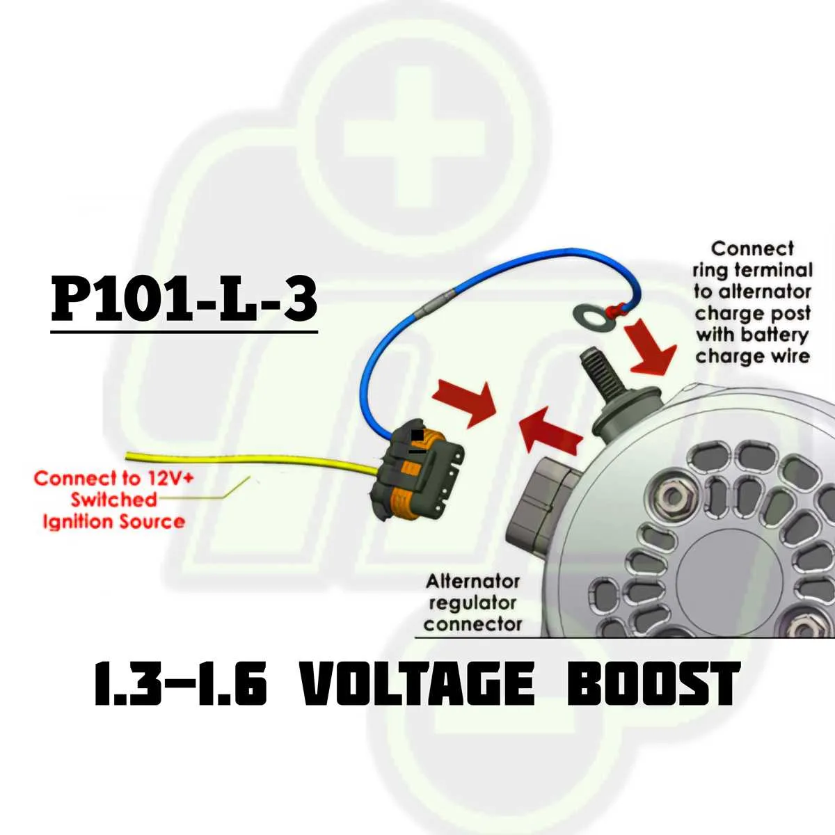
Connect the main charging output (often marked “BAT”) directly to the positive terminal of the battery using a heavy-gauge conductor. This path must handle high current without voltage drop. Use a fusible link rated appropriately for the amperage capacity of the unit.
Terminal 1, usually labeled “excite” or “indicator,” should be linked to an ignition source through a warning lamp or a resistor in the 35–500 ohm range. This line activates the internal regulator when the key is turned on. Without this connection, the system won’t initiate charging.
Terminal 2, marked as “sense,” monitors system voltage. Connect this pin to a point on the fuse block or a junction near the battery to compensate for voltage drop across the system. Avoid looping it directly to the output post; this undermines the regulator’s accuracy.
Always ensure secure grounds between the engine block and the frame. A poor ground can lead to undercharging or erratic system behavior. Use a digital multimeter to verify voltage across the system under load, aiming for 13.8–14.6 volts when running.
3 Wire GM Alternator Wiring Diagram
Connect the battery terminal (often labeled “BAT”) directly to the positive post of the vehicle’s battery using a heavy-gauge conductor. This ensures stable voltage supply under load.
The ignition input (typically terminal 1 on the side connector) must receive 12V switched power. Use a key-on hot lead, ideally through a resistor or indicator lamp, to prevent backfeeding and allow excitation at startup.
Terminal 2, the voltage sense input, should link to a location on the electrical system where voltage drop is likely. Avoid routing it directly to the battery; instead, connect it near the fuse box or main distribution junction for accurate regulation.
Ensure proper grounding through a clean engine block connection. Corrosion or paint at contact points can lead to undercharging or system instability.
Avoid splicing control leads into circuits with fluctuating voltage. Use a dedicated fuse-protected line to preserve system reliability and reduce diagnostic complications later.
Identifying the Functions of Each Terminal (BAT, EXC, SENS)
Connect the BAT terminal directly to the positive post of the battery. It handles the output and is responsible for delivering current to the electrical system and maintaining charge.
Use the EXC terminal (also known as the ignition or indicator connection) to trigger the charging function. Link it to a switched 12V source through a warning lamp or resistor to excite the field coil during startup.
Route the SENS terminal to a point on the electrical bus where voltage accuracy is most critical. This lead compensates for voltage drops in long runs, ensuring correct voltage regulation under load.
Never leave the EXC or SENS terminal floating, as this may lead to undercharging, inaccurate voltage control, or no charge at all.
Step-by-Step Guide to Connecting a 3 Wire GM Alternator to a Vehicle

- Disconnect the negative terminal of the battery to prevent shorts or sparks.
- Locate the rear terminal post labeled “BAT.” Attach a 10-gauge cable from this stud directly to the positive terminal of the battery or starter solenoid post where battery power is supplied.
- Identify the two-pin connector on the side of the unit. Terminal 1 (closest to the battery post) must be connected to an ignition source through a 194-style indicator bulb or resistor (35 to 500 ohms). This activates the excitation circuit.
- Connect Terminal 2 (sense input) to the main battery junction or any point in the electrical system where voltage needs to be regulated. This ensures accurate output control.
- Ensure proper grounding by checking that the case is securely fastened to a clean, unpainted engine surface. Add a ground strap if necessary.
- Reconnect the battery and start the engine. Verify charging voltage at the battery with a multimeter; it should read between 13.8V and 14.6V with the engine running.
Use quality terminals and crimp connectors to prevent voltage drop. Secure all connections away from exhaust and moving components.
Troubleshooting Voltage Drop and Charging Issues in 3 Wire Setups
Start by measuring output directly at the rear terminal using a multimeter with the engine running–voltage should read between 13.8 and 14.7V. If the value drops significantly under load (e.g., headlights on), suspect high resistance in the charge lead or poor ground.
Check the sensing circuit (typically connected to the fuse box or battery junction). A reading lower than the output terminal indicates a drop along the sensing route–reroute closer to the main distribution point if necessary.
Examine the exciter path from the ignition switch to the internal regulator. A dim or non-illuminated charge indicator lamp suggests an open or corroded terminal or insufficient field excitation. Voltage here should match battery potential with key on, engine off.
Inspect all connections for oxidation, fraying, or heat damage. Even a 0.5V drop between the charge output and the battery can result in undercharging. Use dielectric grease after cleaning to prevent further degradation.
If voltage remains low after load testing and lead inspection, confirm rotor resistance is within spec (typically 2–5 ohms) and that brushes have sufficient contact. Replace regulator if field control is unresponsive despite solid excitation.