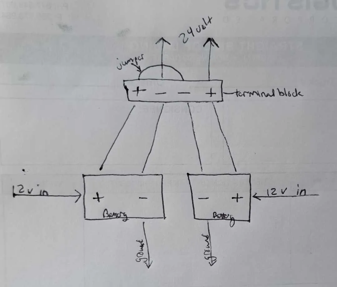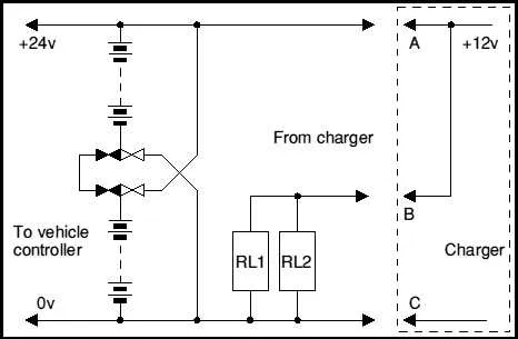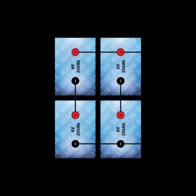
To achieve a 24-volt system using two 12-volt energy cells, place them in series. This configuration allows you to double the voltage while maintaining the same capacity, which is ideal for high-voltage applications.
Begin by linking the negative terminal of the first energy unit to the positive terminal of the second. Then, the free positive terminal of the first unit and the free negative terminal of the second will serve as the outputs for your 24-volt setup. Ensure all connections are secure to avoid short circuits or voltage instability.
Safety Tip: Always double-check polarities before activating the circuit, as reversing them can damage your equipment. Use appropriately rated wire for the current to prevent overheating or power loss.
Note: If more capacity is required, this method can be repeated with additional units, maintaining the series connection to increase the overall voltage output accordingly.
Step-by-Step Guide to Achieving 24 Volts Using Two 12-Volt Units
To achieve the desired voltage of 24 volts, arrange the power sources in series. The process is straightforward, but requires careful attention to polarity and connection points.
- Place the first unit on a flat, stable surface. Identify the positive (+) and negative (-) terminals.
- Join the positive terminal of the first unit to the negative terminal of the second unit.
- On the free terminals, the positive terminal of the second unit should be left exposed, while the negative terminal of the first unit remains unconnected.
- Ensure all connections are secure to avoid any potential short circuits. Use appropriate connectors for safe installation.
- After setup, measure the output using a voltmeter. The combined potential across the free terminals should be 24 volts.
Keep in mind that both units should be of the same type and size for optimal performance. Always verify the specifications before proceeding with the setup.
Wiring Two 12V Batteries in Series for a 24V Output
For a 24V system, link the positive terminal of one power source to the negative terminal of the second unit. This series setup doubles the voltage while maintaining the same current capacity. Ensure that both energy sources have matching capacities (amp-hour rating) for balanced performance.
Use high-quality cables to minimize voltage drops. The wire gauge should be selected based on the expected current draw, with thicker cables preferred for higher loads. Secure connections using appropriate terminals or connectors to avoid weak contact points that can lead to overheating or system failure.
After making the series connection, the remaining positive terminal of the first unit and the negative terminal of the second unit will serve as the output points for your system. The positive terminal of the first and the negative terminal of the second are essentially neutral, making them suitable for the load input.
Consider installing a fuse or circuit breaker for added safety. This will protect the system from potential overcurrent situations and ensure longevity of the equipment.
Choosing the Right Cables and Connectors for a Secure Connection

For a reliable and safe setup, always use cables with a gauge that matches the expected current. A good rule of thumb is to choose a wire that can handle at least 20% more than the maximum current your system will draw. For typical setups, AWG 10 or AWG 8 wires are often ideal.
Wire insulation is also crucial. Ensure that the insulation is rated for the voltage of your system, typically around 600V for automotive and industrial use. Look for cables with a thick, durable coating to protect against abrasions, moisture, and extreme temperatures.
Connectors should be rated for the same voltage and current. Opt for high-quality, corrosion-resistant connectors like those made from tinned copper or nickel-plated brass. They should be able to handle the amperage without overheating, which could lead to failures or hazards.
Consider crimping instead of soldering for most applications. Crimped connections provide a more secure, vibration-resistant bond, especially in environments subject to movement or shocks. Always use a proper crimp tool for optimal results.
Use ring terminals for solid, permanent connections at each end of the wire. These offer superior contact and reduce the risk of loose connections. Ensure that the terminal size matches the cable gauge and that the ring is securely attached to the post or bolt.
For disconnects, employ quality quick-disconnect connectors. These should lock firmly and offer low resistance. This is especially important for easy maintenance or swapping of components in the system.
Testing and Troubleshooting Your 24V Power Setup

Begin by verifying the voltage across both units. Use a reliable multimeter, ensuring that the reading is within the expected range of 24 volts. If the voltage is incorrect, check for faulty wiring or poor connections between the two power sources.
If the system is not providing the correct output, inspect the individual energy cells for damage or corrosion, especially around the terminals. Replace or clean any compromised parts and retest the voltage.
To check the integrity of the link, conduct a load test. Attach a known load to the system and measure the voltage under operational conditions. Significant drops in voltage under load may indicate an issue with the internal resistance or the current-carrying capacity of the setup.
If the setup is charging inefficiently, ensure the charge controller is properly set for the system type. Faulty controllers can result in overcharging or undercharging, which severely impacts system performance and lifespan.
Ensure that the ground connections are secure and free of oxidation. A poor ground can cause erratic behavior or prevent proper function.
If you’re encountering intermittent power loss, check for loose connections or inadequate gauge wires. This can cause resistance to the flow of current, especially under higher demands.
Lastly, always ensure all connections are insulated and protected against short circuits. Exposed wiring can result in sparking or even damage to other components in the circuit.