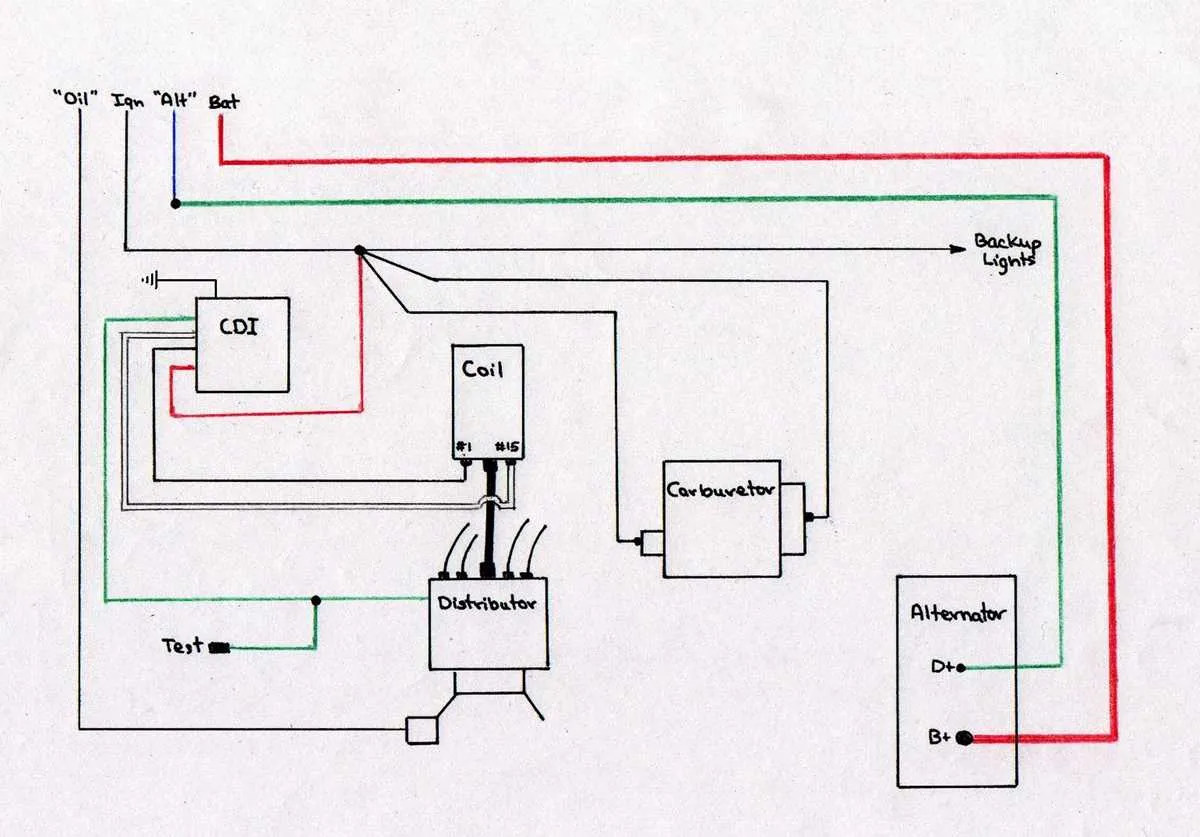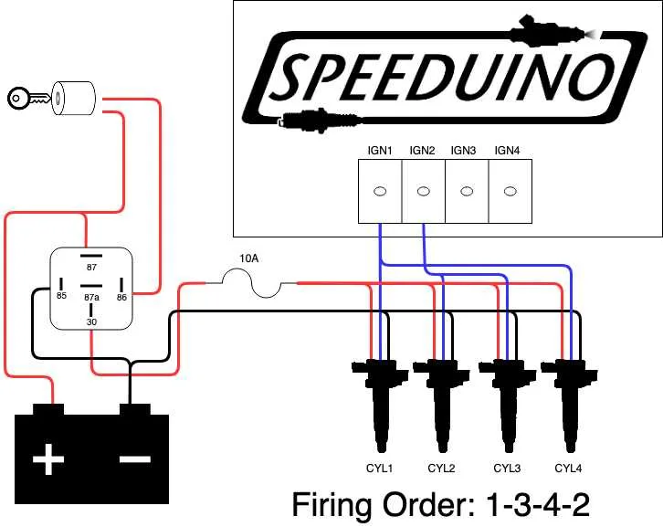
If you’re troubleshooting or setting up a three-terminal spark system, start by identifying the connections: positive, negative, and signal. The positive terminal connects to a power source, the negative to ground, and the signal wire comes from the control unit. This simple setup ensures reliable spark generation under standard conditions.
Correct placement of wires is crucial for optimal operation. Ensure the signal wire properly interfaces with the control unit to trigger energy flow, while the positive terminal maintains a stable connection to your vehicle’s battery or power supply. Any interruption here can result in a misfire or lack of power.
For vehicles equipped with these systems, double-check that the grounding point is solid and free from corrosion. A poor ground connection can cause erratic behavior and affect performance significantly. Moreover, inspect all leads for wear and tear, ensuring that there’s no damage that could interfere with electrical flow.
3-Wire Setup for Spark Device Connections
To properly set up a 3-terminal spark generator, start by connecting the power supply to the positive terminal. This ensures the device receives adequate voltage for operation. The second terminal should be attached to the ground to complete the circuit and prevent electrical interference. Finally, the control signal, which regulates the spark timing, connects to the third terminal. Make sure the signal is stable to avoid performance issues.
Important: Double-check that all terminals are correctly connected to avoid misfiring or damage. A poor ground connection can lead to inconsistent performance. If using a switch for signal control, ensure it functions within the required voltage range.
Ensure all connections are tight and secure to prevent short circuits or loss of power, which could lead to system failures. Regularly inspect the system to ensure optimal performance, especially if the setup is exposed to harsh conditions.
Understanding the Three Connections in a Spark System

For proper functionality, it’s crucial to recognize the role of each connection in a spark system. One connection serves as the power input, typically linked to the battery or the electrical system. This is where the energy needed for generating the spark originates.
The second connection is responsible for grounding, allowing the current to return to the vehicle’s chassis or ground point. This ensures a complete circuit, enabling efficient operation of the component without interruptions.
The third connection handles the signal, which is controlled by the engine control unit (ECU). This regulates the timing and strength of the spark, which directly impacts the engine’s performance and fuel efficiency.
Proper maintenance of each connection is essential. Corrosion or poor contact in any of these parts can lead to misfires, reduced engine performance, or failure to start. Make sure to regularly check for signs of wear or damage to ensure optimal operation.
How to Read the Spark Plug Component Connection Schematic

Start by identifying the three terminals: the positive, negative, and signal terminals. The positive terminal is typically linked to the power supply, while the negative terminal connects to the ground. The signal terminal usually receives input from the control module or switching device.
Next, locate the path from the power source to the component. The current flows through the positive terminal, activating the primary winding, which induces a voltage that flows through the secondary winding, reaching the spark plug.
Understanding the direction of current flow is crucial for troubleshooting. Verify continuity between terminals to ensure proper function. If the current path is interrupted or incorrect, it may lead to firing issues or lack of spark.
Check for any signs of wear or corrosion at the connection points. Poor connections can impede the electrical flow and affect performance. Additionally, ensure that the grounding is secure to avoid potential malfunctions.
Lastly, refer to the schematic’s color coding or labels to ensure each terminal corresponds to its correct function. Incorrect wiring can cause electrical failures or misfires, resulting in poor engine performance.
Common Wiring Issues and How to Fix Them
If you’re facing electrical problems with your engine system, check the following common issues:
- Loose Connections: Ensure all terminals are securely fastened. If the connectors are worn or corroded, replace them to prevent intermittent connections.
- Short Circuits: Inspect the circuit for any signs of exposed cables or damaged insulation. Replacing or rerouting the affected wires is essential to restore proper function.
- Faulty Grounds: Ensure the grounding points are free from rust or dirt. Clean and tighten all grounding connections to eliminate electrical resistance.
- Incorrect Voltage Supply: Verify that the voltage matches the required input for your system. Use a multimeter to check for consistent power flow and replace the regulator if necessary.
- Broken or Damaged Cables: Inspect for fraying or cuts along the cable path. Any damaged cables should be replaced immediately to avoid failure under load.
To prevent recurring issues, it’s recommended to use high-quality components and periodically inspect the system to identify early signs of wear.