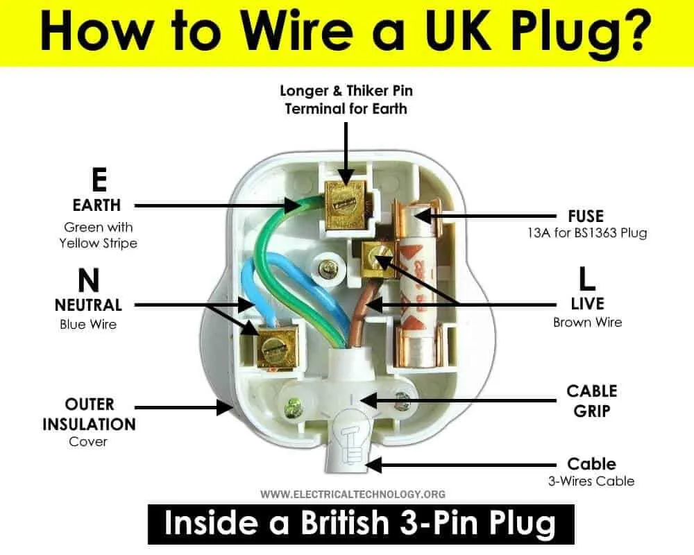
For safe and efficient electrical connections involving three conductors, it is essential to follow the standardized color coding and terminal arrangement. Typically, the green or bare conductor must be attached to the grounding terminal, ensuring proper earthing and safety from electric shocks. The remaining two leads carry the live current: one is the neutral, usually white or blue, and the other is the active, often black or brown.
Precise identification of each conductor before attaching them to the corresponding pins prevents malfunctions and hazards. Using a tester or continuity checker guarantees that each line matches the correct terminal, avoiding reversed polarity and short circuits. Secure fastening is crucial to maintain stable contact and reduce electrical resistance.
When assembling or inspecting the connection assembly, always adhere to local electrical codes and manufacturer instructions. Employing appropriate tools such as insulated screwdrivers and strain relief clamps improves durability and safety. Confirming the integrity of the setup with a voltage tester after completion provides an extra layer of verification for operational reliability.
3 Wire Plug Diagram
Connect the live conductor to the terminal marked with “L” or colored brown for standard identification. The neutral lead should attach to the point labeled “N” or blue-coded connection. The earth conductor must link firmly to the green/yellow terminal, ensuring proper grounding and safety compliance.
Confirm all terminals are securely tightened to prevent any loose contacts that could cause overheating or electrical faults. Use a screwdriver suitable for the terminal screws, applying firm pressure without damaging the connectors.
Follow polarity standards strictly to guarantee the correct flow of current and avoid potential hazards. The arrangement of the three contacts must mirror the recommended configuration specified by national electrical codes.
Inspect insulation integrity before final assembly, making sure no exposed metal parts remain that could lead to short circuits or shocks. Proper insulation maintains the durability and reliability of the connection over time.
Test continuity and grounding with a multimeter after completing the setup to verify that all paths are correctly established and safe for operation. This step is critical to confirm the functional integrity of the assembled connector.
How to Identify Each Wire in a 3 Wire Plug

Start by identifying the function of each conductor based on color. The green or green-yellow striped conductor is typically the ground. It should be connected to the earth terminal to ensure safety.
The live conductor, usually colored brown or red, carries the current to the device. This is always connected to the terminal labeled with a “L” (for Live).
The neutral conductor is commonly blue. It is connected to the terminal marked with an “N” and completes the circuit by carrying the return current.
Before handling any connections, ensure the power supply is turned off. Use a multimeter to check the continuity of each conductor to confirm proper identification.
When attaching the conductors, ensure they are securely fastened to avoid any loose connections, which could lead to malfunction or hazards.
Step-by-Step Wiring Instructions for a 3-Wire Connection
1. Begin by identifying the three terminals: live, neutral, and ground. The live terminal is usually marked as “L,” the neutral as “N,” and the ground terminal as the symbol of a vertical line with three horizontal lines underneath.
2. Prepare the conductors. Strip off approximately 1 cm of insulation from each end of the cables, ensuring the exposed metal is clean and free from damage.
3. Attach the live conductor to the terminal marked “L.” Ensure the metal is securely fastened under the terminal screw, with no exposed wire beyond the terminal. Tighten the screw firmly.
4. Connect the neutral conductor to the “N” terminal, repeating the same process as with the live connection. Double-check that the metal conductor is fully inserted and the screw is tight.
5. Connect the ground conductor to the ground terminal. If necessary, loop the conductor around the screw in a clockwise direction, ensuring a solid connection. Tighten the screw securely.
6. Check that no stray wires are sticking out or making contact with the housing. The connection should be clean and the conductors well-insulated, ensuring safety during operation.
7. Once all connections are made, inspect the assembly for stability. Gently pull on each wire to ensure the connection is firm and there are no loose ends.
Important: Always verify that the power is switched off before starting the installation process. A multimeter can be used to double-check the absence of electrical current.
Final Check: Ensure that the casing is correctly aligned and the cover is securely fastened to prevent any exposure to electrical components.
Common Troubleshooting Tips for 3 Wire Connections
If you’re encountering issues with a three-terminal setup, follow these steps to identify the problem quickly.
- Check for loose connections: Ensure that all terminals are securely attached to their respective contacts. A loose connection can cause intermittent or no power flow.
- Inspect for corrosion: Corrosion on the contact points can lead to poor conductivity. Clean any corrosion with an appropriate cleaning solution or wire brush, ensuring a solid connection.
- Verify correct terminal identification: Double-check that each lead is connected to the correct terminal–neutral, live, and ground. Incorrect placement can cause safety hazards or equipment failure.
- Test continuity: Use a multimeter to test the continuity of each path. No continuity suggests a break or damaged section in the circuit.
- Examine for shorts: Ensure the terminals are not touching each other or shorting against a metal surface, which can cause a short circuit and potential damage.
- Check for frayed or damaged insulation: Any visible damage to the insulating material can lead to short circuits or grounding issues. Replace damaged sections immediately.
- Evaluate the ground connection: A faulty ground can lead to electric shock or equipment malfunctions. Ensure the grounding lead is firmly attached to a metal part that offers a reliable connection to the earth.
Regularly maintain and inspect your setup to avoid performance issues and enhance safety.