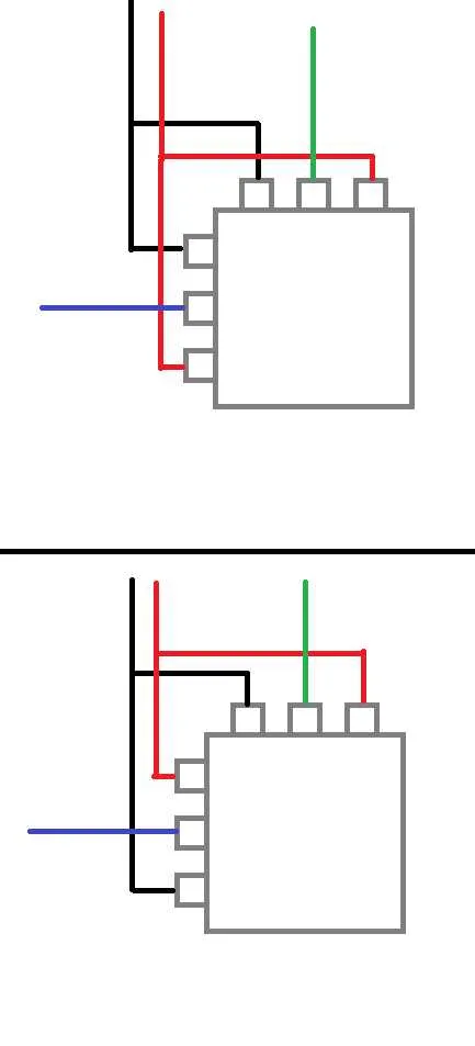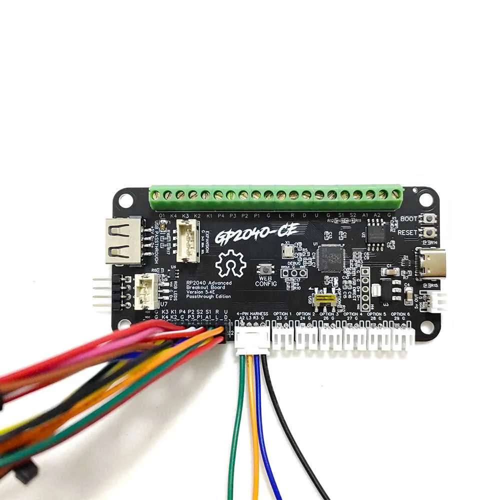
To ensure seamless functionality in game controllers, focus on the precise routing of electrical connections and components. Properly arranging the paths between the microcontroller, input buttons, and output interfaces is crucial for smooth data transmission and power distribution. The key is to maintain clear, short paths to minimize signal interference and ensure fast communication across the device.
Attention to grounding is vital. A robust ground system reduces noise, stabilizes voltage levels, and prevents unwanted interactions between signals. Connect all ground points with low-resistance traces to create a unified electrical environment, ensuring minimal fluctuations in signal strength.
Another critical factor is the careful selection of conductive tracks for high-speed signals. Use wider routes for power lines and thinner ones for control signals, balancing both speed and efficiency. Keeping high-frequency signals away from power lines helps maintain signal integrity and reduces the likelihood of cross-talk.
When designing the layout, ensure that each component’s placement is optimized for electrical performance and ease of accessibility. Align connectors and other interfaces to align with the device’s form factor while ensuring no interference with other crucial paths. By maintaining these key principles, you’ll build a durable, reliable, and efficient game controller.
Wiring Layout for Controller Boards

Ensure proper connections by carefully following the schematic for the input-output pins. Use a multi-layer board design to separate high and low voltage paths, which minimizes interference. For microcontroller integration, ground planes should be continuous and well-defined to reduce noise. Always verify the pinout alignment before soldering; incorrect mapping can result in erratic performance or device malfunction.
Opt for high-quality soldering materials, and avoid over-heating the components during the process. If using ribbon cables or connectors, choose ones with low resistance to maintain signal integrity. Pay special attention to the routing of power lines, ensuring minimal length to avoid voltage drops that could impact device performance.
For debugging, employ a multimeter to check continuity and resistance on all traces, confirming that no unintended shorts or open circuits are present. For precise placement, consider using a magnifying tool or microscope to inspect small components and avoid damaging fragile connections.
When dealing with external switches or connectors, ensure that each is securely attached, with an appropriate strain relief to avoid stress on the solder joints. Organize your wiring to minimize crossing of power and data lines, as this can lead to electromagnetic interference (EMI) that affects signal quality.
Finally, when finalizing the build, conduct thorough testing in various environmental conditions to ensure that all connections hold up under stress and temperature changes. This will provide a reliable and stable setup for the entire system to function smoothly.
Understanding the Components in a Circuit Board Layout

When analyzing the layout of a circuit board, identifying key elements is crucial for efficient troubleshooting and modification. First, pay attention to the power lines, which distribute current to different sections. Ensure they are appropriately routed to minimize voltage drop and avoid overloading. A common issue arises when traces are too narrow for the current they carry, leading to overheating or failure.
Next, observe the capacitors and resistors, which regulate voltage and current. Proper placement of these components is essential for stability and performance. Capacitors should be near the power input, while resistors typically control the current flow to sensitive components. The value and tolerance of each component should match the circuit’s requirements to avoid malfunction.
Also, the microcontroller or main processing unit will often be the heart of the system. Its connections must be solid and its pin configuration properly adhered to. Incorrect connections can result in malfunction or failure to initialize. Ensure that the ground and power pins are securely connected to avoid unstable operation.
Lastly, don’t overlook the importance of connectors and switches. These facilitate communication between the board and external devices. Faulty or improperly soldered connectors can disrupt signals or cause complete system failure. Verify that all external interfaces are clearly marked and well-protected from short circuits.
Step-by-Step Guide to Reading and Interpreting a Circuit Schematic

To effectively understand the layout and connections within a printed circuit, start by familiarizing yourself with key components and their functions. Follow these steps to break down the schematic in a logical way:
- Identify Key Components: Begin by locating resistors, capacitors, diodes, and integrated circuits. Each of these will have specific symbols, so recognize these first.
- Understand Pinouts and Connections: Focus on the component’s pinout. These are crucial for understanding how current will flow and where connections should be made.
- Check Ground and Power Lines: Look for the ground symbol (often represented by a downward triangle) and power supply lines. These are critical to ensure the circuit works properly.
- Trace Signal Paths: Identify how the electrical signals travel between components. Follow the lines and ensure that they connect correctly, without breaks or shorts.
- Look for Junctions: Junctions (where lines meet) often denote branching of power or signals. These should be clearly marked with dots in most cases.
- Verify Component Values: Check the values of resistors and capacitors, which are often marked on the components or beside them on the schematic. These values are critical for proper functioning.
When examining the connections, use the following tips to avoid mistakes:
- Verify continuity between adjacent components using a multimeter.
- Double-check the connections against known working configurations if you’re troubleshooting.
- Compare the layout to physical boards if available to see how real-world connections match up with the schematic.
Finally, always ensure that you work methodically, section by section, avoiding the temptation to rush through complex parts. Thorough analysis is key to understanding how everything fits together.
Troubleshooting Common Issues in Circuit Board Connections

Ensure that all connections are secure and properly soldered. Cold or weak solder joints can cause intermittent signals or complete failure. Inspect each joint closely for any signs of cracks, gaps, or insufficient solder.
If the device isn’t powering up, check the power lines for continuity and proper voltage. Use a multimeter to confirm that the power supply is delivering the expected voltage to the board, and that ground connections are intact.
Verify that the signal traces are not shorted. A simple visual inspection can reveal physical damage, such as burns or pinched traces. If there are damaged paths, consider rerouting or repairing them with conductive tape or jumper wires.
Check for any components that may be incorrectly oriented. Misplaced diodes, transistors, or capacitors can lead to erratic behavior. Cross-check component placements with the manufacturer’s specifications to ensure correctness.
Confirm the compatibility of all connected peripherals or external devices. Incompatibilities, such as mismatched voltage levels or unsupported communication protocols, can result in malfunction. Look for signs of overheating or miscommunication on connected hardware.
If the system is unstable or intermittently fails, try isolating each part of the system. Disconnect or remove non-essential components one by one to pinpoint the source of instability.
Check for any unwanted signal interference, especially if the system operates in a noisy environment. Add decoupling capacitors close to critical components to minimize noise and reduce the chance of unpredictable behavior.