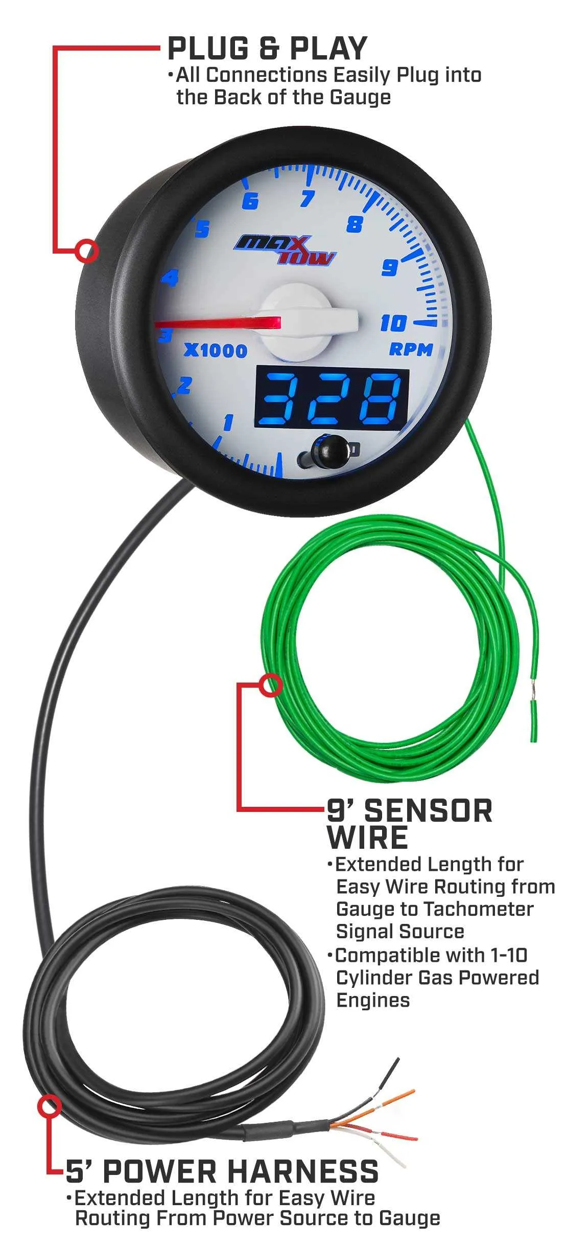
For accurate engine speed monitoring, ensure proper connection of the four essential terminals. The first terminal, typically marked as signal input, is critical for receiving the frequency data from the engine’s control system. Make sure it’s connected to the output terminal of the sensor that measures the revolutions per minute.
The second terminal should be linked to ground to complete the circuit, ensuring all components function correctly. Without a stable connection to the ground, the system may malfunction, leading to inaccurate readings or failure to display engine RPMs.
Next, connect the third terminal to the positive voltage supply, which powers the entire monitoring unit. This connection must be secure and sourced from a reliable power outlet to ensure consistent operation.
Finally, the fourth terminal is often reserved for backlight or illumination features. In some setups, this terminal can be used for enhanced visibility, while in others it serves as an auxiliary connection for added functionalities. Double-check compatibility before making this connection to avoid overloading any circuits.
4 Wire Tach Wiring Diagram
To connect a 4-wire instrument for RPM measurement, ensure each terminal is connected as follows:
1. The first terminal is for the positive power supply. This should be connected to a reliable 12V source.
2. The second terminal is the signal input, which monitors engine pulses. This should be routed to the ignition system or pulse-generating component.
3. The third terminal is for ground. Secure this connection to a solid chassis ground to avoid erratic readings.
4. The fourth terminal is for the output to the display or controller. Connect this to the display unit for accurate RPM readout.
Verify each connection to ensure proper signal transmission. A poor connection can lead to incorrect readings, affecting overall performance monitoring. Always use high-quality connectors and ensure there are no loose or corroded contacts. Double-check that the input is connected to a pulse signal, such as from the ignition coil, for accurate operation.
Testing should be done with a multimeter before full operation. Ensure that each wire is properly insulated and routed away from heat sources to prevent degradation over time. The power supply connection should be fused for added protection against electrical surges.
Understanding the 4 Pin Sensor Connection Layout
The 4-pin configuration typically includes the following: one pin for power, one for ground, one for signal input, and one for output. The power pin should be connected to a 12V source, while the ground pin connects to the system’s common ground. The signal input pin receives the pulse from the engine or motor, providing data for measurement. The output pin transmits the processed information to the monitoring unit for display.
For accuracy, ensure that the signal input pin is linked to the correct source that generates pulses at a consistent frequency. This pulse frequency directly correlates to the monitored parameter. The output pin will send this data to your gauge or display, allowing you to monitor the system’s performance in real time.
Double-check the voltage ratings before making connections to prevent damage to the system. Ensuring proper polarity and matching the correct pins to their respective functions is crucial for reliable performance.
Common Issues with 4 Pin Sensor Connections and How to Fix Them
When connecting a 4-pin sensor for RPM reading, the following issues may arise:
- Incorrect Grounding: Ensure the ground connection is secure. A poor ground can result in erratic readings or failure to display RPM. Double-check the ground pin and its connection to a solid ground point on the vehicle or equipment.
- Loose or Corroded Connectors: Inspect all connectors for corrosion or looseness. Corrosion can interfere with proper signal transmission. Clean and tighten all connections using appropriate tools.
- Signal Interference: High-voltage components nearby may cause electrical noise. If interference is suspected, try adding a filter or rerouting the signal cable away from these sources.
- Incorrect Signal Source: Verify that the signal pin is receiving input from the correct sensor. Some sensors output different signal types, such as analog or square wave. Ensure compatibility with the receiving unit.
- Wrong Voltage Supply: Check the power supply voltage. A mismatch between the sensor’s required voltage and what is provided can prevent it from functioning correctly. Use a multimeter to confirm the voltage levels at the supply pin.
To resolve these issues, take a systematic approach: check for proper grounding first, clean connectors, eliminate interference sources, and ensure compatibility between the sensor and the system.
Connecting a 4 Wire Tachometer to Your Engine: Step-by-Step Guide
Begin by identifying the four terminals on your instrument. Each one serves a distinct function: power, ground, signal input, and output. Ensure that the device is off before proceeding to prevent electrical shorts or damage.
First, connect the power terminal to a 12V supply from your engine’s electrical system. This is typically linked to the ignition circuit to activate the unit when the engine starts. Make sure the power supply is stable and capable of providing adequate voltage.
The ground terminal must be connected to a solid metal surface on the engine block or chassis. Ensure this connection is clean and free from paint or rust to prevent poor contact.
Next, connect the signal terminal to the engine’s pulse output, which can be found on the ignition coil or other sensor points that provide timing signals. Check your engine’s manual for the exact location of this output point.
Finally, link the output terminal to your monitoring system or control module, if applicable. This allows for the proper transmission of data for analysis or display purposes.
After all connections are made, double-check the integrity of each connection, making sure there are no loose terminals or exposed conductors. Once satisfied, test the system by starting the engine and verifying the readings on your display unit.