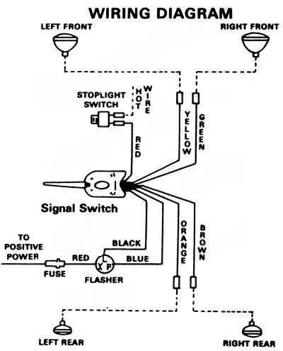
For effective setup and troubleshooting of emergency warning lights, focus on correctly wiring each component. Properly connecting the light assembly to the power source is critical for reliable functionality. Start by identifying the terminals that control power input and output, ensuring they are securely attached to the right points in the circuit.
Next, pay close attention to the grounding connections. A common mistake is improper grounding, which can cause the system to malfunction or become unstable. The negative terminal should always be connected to a grounded point on the vehicle or structure.
Also, ensure that you are using the correct wire gauge to handle the current load. Using wires that are too thin can result in overheating or reduced performance. Consult the manufacturer’s specifications for wire size and fuse ratings to prevent damage to the components.
For optimal performance, verify that all connections are made with high-quality terminals and connectors. Corrosion or loose connections can lead to intermittent failures. Once all wiring is completed, perform a test to confirm that the system functions as expected under different conditions.
By following these steps, you will not only enhance the reliability of your emergency light setup but also avoid costly repairs or replacements due to wiring errors.
Wiring Guide for Flashing Light System

Start by connecting the positive terminal of the power source to the control switch. Ensure the switch is rated for the voltage of the lighting unit. The wiring should follow the specifications of the system’s power capacity to avoid overloading.
The ground wire needs to be securely attached to the vehicle frame or a designated ground point. For optimal performance, use corrosion-resistant connectors to prevent deterioration over time.
The light assembly typically has two leads: one for the hot connection and another for the ground. The hot lead connects to the power switch, while the ground lead attaches directly to the ground point. If your setup includes multiple lights, ensure each is wired in parallel for consistent brightness across all units.
If you are integrating a flasher unit, connect the signal input from the switch to the flasher’s control wire. The output from the flasher unit then goes to the light assembly. Double-check the polarity of the wires to avoid malfunction.
For added safety, use a fuse or circuit breaker rated for the power draw of the lights. This will protect the system from potential electrical surges or short circuits. Make sure all wires are properly insulated to avoid accidental shorts or damage during use.
Finally, verify the entire setup by testing the system before permanent installation. Ensure all connections are secure and that the light flashes in sync with the switch activation.
Understanding the Basic Electrical Setup for 900 Models
For optimal performance, ensure the power leads are securely connected to the appropriate terminals. Typically, the positive wire should be linked to the power supply, while the ground wire connects to the chassis for a reliable grounding point. Double-check the integrity of these connections before powering up the system.
The indicator lamps rely on a consistent current flow, and their wiring should follow a specific path to ensure proper signaling. The connection of the light’s positive terminal to the control switch must be tight to prevent any interruptions in operation. Similarly, the negative terminal should connect securely to the ground point, ensuring proper circuit completion.
Key Tip: Verify that each wire is properly insulated and routed to avoid any accidental short circuits. Running wires too close to heat sources or sharp edges can lead to premature wear and eventual failure of the system.
When linking multiple units in a series, it is crucial to ensure that each component receives the correct voltage. Use a multimeter to measure voltage at each terminal to confirm that the components are receiving consistent power levels. Any deviation from the expected voltage can lead to malfunctions or failure to operate altogether.
Additionally, for vehicles or machines with multiple units, ensure that the signal elements are connected in parallel to maintain uniformity in their function. This way, the failure of one unit will not affect the entire system.
Pro Tip: Always route the cables in a way that avoids excessive tension on connections, especially during movement. Secure all wires with proper fasteners to prevent damage over time from vibration or friction.
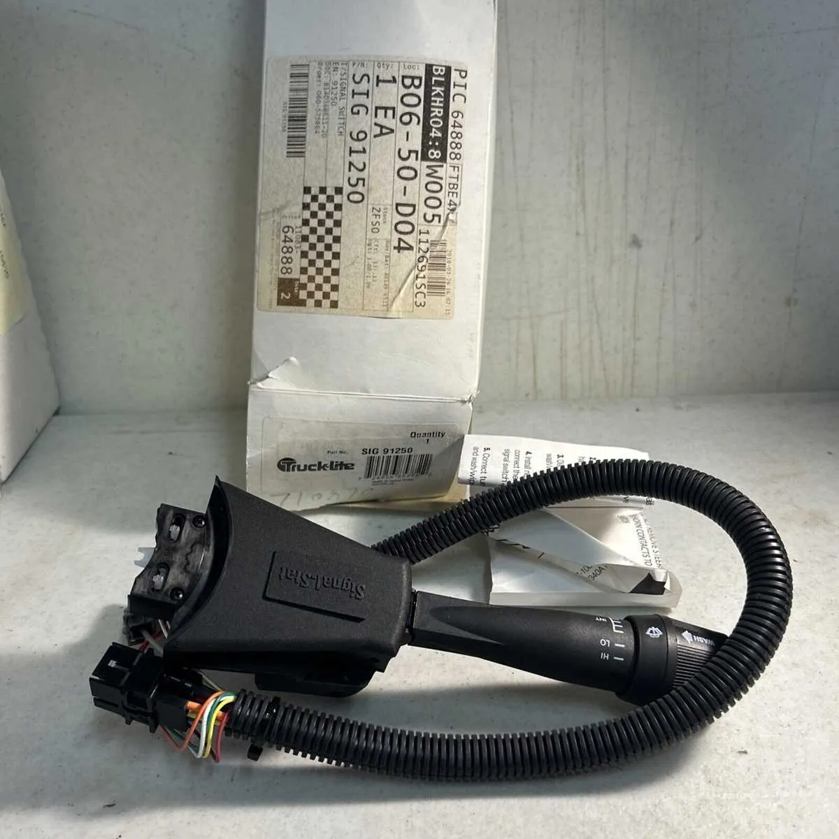
Step-by-Step Guide to Properly Connecting Wires for 900 Signal Stat
Ensure you follow the correct sequence when attaching each wire to avoid malfunction. The process involves several key steps for safe and effective installation.
- Turn off the power: Always disconnect the power supply before working with electrical components to prevent any risk of shock.
- Identify the terminals: Familiarize yourself with the component’s connection points. Typically, these will be clearly marked. Look for labels such as “Power,” “Ground,” and “Input.”
- Prepare the wires: Use wire strippers to remove insulation, exposing enough of the wire to make solid connections. Be sure not to strip too much.
- Connect the ground wire: Begin by attaching the ground (negative) wire to its designated terminal. This is often marked with a negative symbol (-) or “GND.” Ensure it’s tightly secured.
- Attach the positive wire: Next, connect the power (positive) wire to the corresponding terminal. This is commonly labeled with a plus sign (+) or “PWR.” Check for any loose connections.
- Insert the signal wire: This wire will typically go to the input terminal. Secure it firmly to ensure reliable functionality. Verify its connection with a multimeter before moving forward.
- Test continuity: Before finalizing, use a multimeter to check continuity and confirm all connections are correct.
- Reattach the power: Once satisfied with the connections, re-enable the power supply and test the system to ensure proper operation.
Double-check each connection before powering up the system to avoid potential issues. If you encounter problems, retrace the steps and verify the wiring is secure and correct.
Troubleshooting Common Electrical Problems in Vehicle Lighting Systems
Start by verifying the power supply. If lights aren’t functioning, check if the fuse is blown or if there’s a loose connection at the power input. Ensure the circuit has no breakages or corroded terminals.
Inspect the ground connection. Poor grounding is a frequent cause of malfunction. Ensure that the wire is securely fastened to a clean metal surface, free from rust or paint.
Check the indicator connections, particularly the switching mechanism. A faulty relay or switch can cause intermittent operation or complete failure. Test the switch with a multimeter to confirm it’s functioning correctly.
Examine the bulb socket. Corrosion or dirt buildup can interrupt the electrical flow. Use contact cleaner to remove any debris and inspect for worn-out or damaged terminals that may need replacement.
Verify the connection to the indicator bulbs. A common issue is the presence of an open circuit where the bulb isn’t seated properly or the contacts are loose. Confirm that the bulb is correctly installed and making contact with the system’s terminals.
If the system operates but with reduced brightness or flickering, check for resistance in the wiring. Damaged insulation or weakened wires can increase resistance and lower voltage, leading to poor performance. Replace any damaged sections of the cable.
Lastly, for systems using multiple light units, ensure that the wiring can handle the load. Overloading the circuit can lead to overheating and malfunction. Recheck the power requirements of each unit and ensure the wire gauge is appropriate for the current draw.