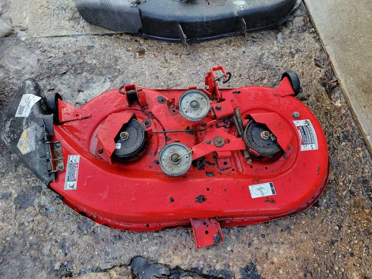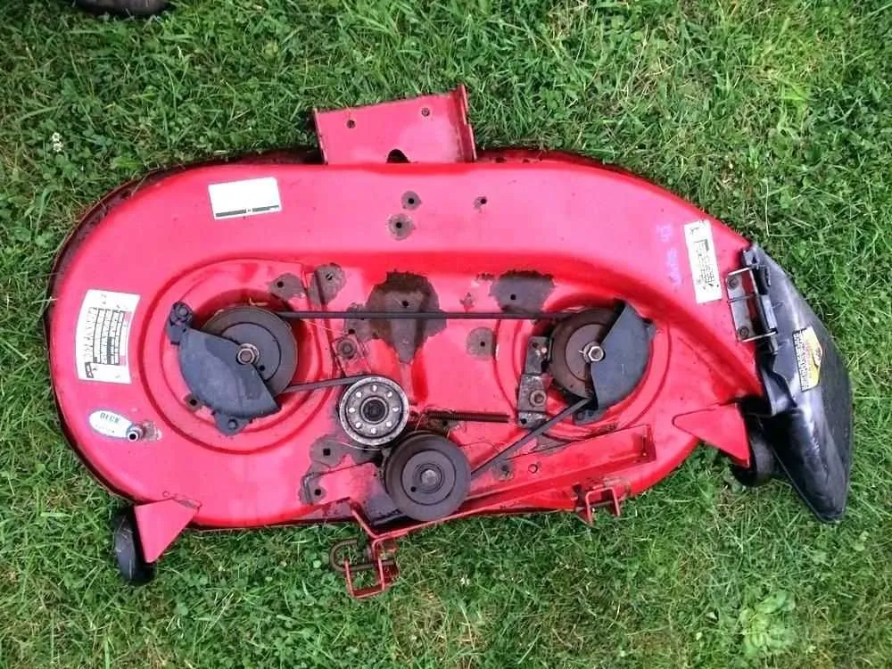
Start by attaching the extension coil to the idler arm bracket located on the right side of the cutting platform. This component connects to the belt tensioning mechanism and ensures proper alignment during operation. Secure it using the factory-designated eyelet and verify the hook orientation matches the service manual layout.
Next, fasten the secondary recoil element between the clutch lever and stabilizing post near the frame mount. Ensure it passes beneath the drive pulley and does not interfere with the blade rotation path. Misalignment here can cause premature wear or failure of the traction linkage.
Check the routing pattern for both front and rear retention coils. The forward unit loops through the pivoting hanger, while the rear one connects to the lift assist bracket. Pay close attention to which tab each loop secures to–incorrect placement will affect cutting height consistency.
Once all coils are mounted, apply tension manually before engaging the control lever. Rotate the blades by hand to confirm there is no binding. A common mistake is reversing the rear loop orientation, which can cause disengagement when lowering the platform.
Tip: Always compare your installation with a manufacturer schematic or photo reference before use. Components often vary slightly depending on production year or model revision.
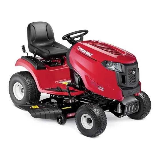
42 Inch Troy Bilt Pony Deck Spring Diagram

Begin by positioning the tension coil between the idler arm and the anchor bracket beneath the mower frame. Ensure the looped end connects firmly to the slotted opening on the movable arm, while the hooked end attaches to the stationary mount near the chassis rail.
Correct alignment is critical: the elastic component must run parallel to the belt routing to maintain pulley engagement during blade operation. Misalignment often causes premature wear or disengagement during use.
Use a flathead tool to guide the metal coil into place without overstretching. Avoid using pliers that can deform the loops. When installed, the component should have moderate tension with no slack or excessive strain.
Refer to the underside bracket near the right spindle housing–this is where the secondary recoil loop often connects, depending on the model year. Cross-reference the part number stamped near the rear hanger to ensure compatibility.
Before testing, confirm all moving arms return to position smoothly when released. If the mechanism binds or feels unstable, recheck both mounting points and confirm the routing path follows the original layout.
Spring Locations on the 42 Inch Troy Bilt Pony Mower Deck

Start by locating the tension coil near the idler arm; it stretches diagonally from the pulley bracket to a welded eyelet on the frame’s left side. Ensure it’s secured with a cotter pin to prevent detachment during blade engagement.
The assist coil connects the blade engagement mechanism to the control lever assembly. Positioned just behind the front right wheel, it links the lever bracket to the tensioning arm via a hooked end. Replace immediately if overstretched to maintain correct engagement force.
A smaller recoil unit is mounted horizontally between the clutch control arm and a fixed post near the frame center. It retracts the drive mechanism when disengaged. Inspect the mounting holes for wear that may affect performance.
On the rear underside, a stabilizing unit runs from a pivot bracket near the discharge chute to a fixed stud behind the pulley cover. This one maintains belt alignment during operation. Look for fraying or corrosion on the hook ends.
Identifying and Replacing the Tension Component in the 42 Model Mower Platform

Begin by parking the mower on a flat surface, engaging the parking brake, and removing the ignition key. Disconnect the spark plug wire to prevent accidental starts.
- Lower the cutting platform to its lowest position using the height adjustment lever.
- From the right side, locate the coiled metal element near the idler pulley arm–it connects the movable arm to a fixed point on the chassis frame.
- Check for signs of wear: elongation, rust, or breakage. A weakened coil can result in belt slippage and uneven cutting.
To remove the worn-out part:
- Use needle-nose pliers to unhook it from the fixed frame anchor.
- Release the opposite end from the idler assembly. Keep fingers clear of pinch points.
Install the replacement by reversing the steps:
- Attach one end to the stationary bracket first, ensuring it’s fully seated in the slot.
- Use a flat-head screwdriver for leverage when connecting it to the movable pulley arm.
- Verify full movement of the tensioning system by rotating the pulley by hand. There should be no binding or slack.
Always use a manufacturer-approved replacement part with identical coil gauge and length. After reassembly, reconnect the spark plug, start the mower, and engage the blades briefly to confirm tension is correct.
Routing the Return Spring for Proper Blade Engagement
Attach the recoil tensioner to the rear mounting point on the mower frame, directly behind the blade engagement arm. Ensure the coiled end loops securely around the anchor pin without slack.
Guide the opposite hook through the rear slot of the tension bracket located near the left pulley housing. Avoid routing the coil underneath any belt guard or across the idler pulley shaft to prevent misalignment.
Confirm that the hook sits above the pivot arm’s flange, not below it, to maintain correct rebound force. Improper placement can delay blade disengagement and wear out the cable linkage.
| Component | Attachment Point | Routing Note |
|---|---|---|
| Recoil Hook | Rear frame anchor | Must loop securely with no stretch |
| Opposite End | Rear slot in tension bracket | Do not route under pulley shaft |
| Middle Path | Above pivot flange | Ensures proper alignment and tension |
After installation, test blade activation by engaging the lever slowly. The recoil should snap the mechanism back fully when released. If movement is sluggish or incomplete, recheck alignment points and retighten any loose fasteners.