Always disconnect the power supply before accessing any control modules. Use a multimeter to confirm zero voltage across all contacts. Failure to do so may result in short circuits or damage to internal components.
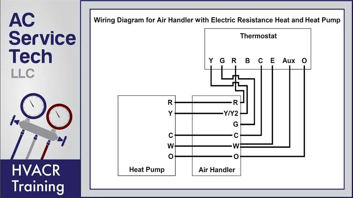
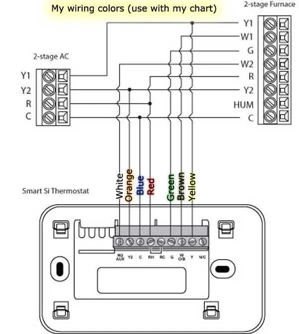
For most models, connect the red lead to the 12V DC power source, typically labeled as “R” or “RV+.” The white conductor usually corresponds to the heat control signal and links to the “W” terminal. Fan operation is managed by the green wire, commonly tied to the “G” point. If your setup includes cooling, the yellow line connects to the cooling relay, often marked as “Y.”
Older configurations may include a blue wire for common ground or auxiliary control. Confirm pin layout against the manufacturer’s specifications, as layouts differ between analog and digital units. When integrating with a combo heating/cooling system, ensure proper isolation between control circuits to prevent backfeeding.
Label every cable during disassembly to avoid confusion during reassembly. Take clear photos before removing any connectors. If upgrading to a programmable control unit, verify compatibility with both single and multi-stage equipment.
Never splice conductors without proper junction caps or crimp connectors. Loose or exposed joints can cause intermittent faults or fire hazards during travel vibrations. Secure all cabling with clips to prevent chafing against metal surfaces.
RV Thermostat Wiring Diagram

Start by disconnecting the 12V DC supply before interacting with any control lines. For units using a 4-wire setup, connect the red lead to the power source (+12V), white to the furnace relay, green to the fan circuit, and blue or yellow to the cooling function. Label each conductor during removal to prevent confusion.
In dual-zone systems, use a 7-conductor harness. Pin 1 typically delivers voltage, while pins 2 through 7 handle separate HVAC triggers. Always verify pinout against the control board’s specifications, as color schemes may vary between brands.
For digital controllers, a communication bus (commonly marked “COM” or “Data”) might replace individual signal paths. These require correct polarity–reversing data lines can disable the interface or cause erratic operation.
Use a multimeter to confirm continuity and voltage at each connection. Avoid splicing or twisting bare wires–secure all junctions with crimp connectors or terminal blocks rated for mobile environments to withstand vibration and temperature changes.
How to Identify and Label Thermostat Wires in an RV System
Start by disconnecting all power sources: shore power, generator, and battery. This prevents accidental shorts or damage to control units.
- Remove the faceplate from the control panel and expose the connected leads.
- Use a multimeter to test each conductor for voltage. Tag any live lines and verify their origin.
- Look for standard color codes:
- Red (R): 12V power from fuse panel or converter.
- White (W): Heat trigger to furnace control board.
- Yellow (Y): Cooling signal to compressor relay.
- Green (G): Fan relay (often for air handler control).
- Blue or Black (C): Common return (used with digital controllers).
- Apply adhesive labels or shrink tubing to each cable end based on function. Avoid using electrical tape; it degrades over time.
- Document all connections in a manual or label diagram inside the service hatch for future reference.
In older mobile systems or modified units, conductors may be miscolored or repurposed. Confirm each function with continuity testing and system-specific documentation before reconnecting any terminals.
Step-by-Step Guide to Connecting a New RV Thermostat to a Furnace and AC Unit
Disconnect power from the control board and HVAC system to avoid short circuits or injuries.
Label each existing conductor according to its terminal on the old control panel: typically, G for fan, W for heating trigger, Y for cooling, R for power (12V or 24V), and common (C) if available. Take a clear photo for reference.
Detach the old controller and verify conductor integrity–no exposed copper or corrosion. Replace any damaged segments with matching gauge, preferably 18 AWG solid core.
Mount the new unit’s base securely, ensuring it’s level and accessible. Avoid metal surfaces to reduce interference. Pass each conductor through the opening and connect based on the terminal labeling scheme:
- R to red (power supply)
- G to green (fan control)
- Y to yellow (compressor)
- W to white (heat relay)
- C to blue or black (if needed for digital units)
Tighten terminal screws securely to prevent contact loss. Confirm no bare conductor is exposed beyond the connector.
Reconnect the system’s power and test both cooling and heating cycles. Adjust fan settings and verify the blower activates appropriately in manual and automatic modes.
Monitor startup behavior and response lag. If the furnace fails to ignite or the compressor doesn’t engage, recheck the control board fuses and confirm polarity.
Troubleshooting Common RV Thermostat Wiring Issues After Installation
Begin by verifying all terminal connections match the control unit’s specifications–commonly labeled as R (power), W (heat), Y (cool), G (fan), and C (common). A mismatch in terminal pairing often causes fan malfunctions or system silence. Use a multimeter to confirm 12V or 24V presence at the R contact point depending on your setup type.
If the blower runs continuously, check for a short between G and R leads. Disconnect the control panel and inspect for continuity where there shouldn’t be any. Replace damaged conductors or corroded connectors immediately.
In cases where heating or cooling fails to start, measure voltage across R and W (for heat) or R and Y (for cooling). Zero reading indicates an open circuit–inspect inline fuses, blade terminals, or mechanical switches near the HVAC board.
Unresponsive displays often result from a missing common return (C). If your interface requires constant power and C is unused, install a DC-DC converter or run a dedicated return line from the control board to the interface module.
When dealing with intermittent function, perform a continuity check under vibration conditions. Tug each line gently while monitoring resistance. Poor crimps or internal strand breaks tend to reveal themselves under minor motion.