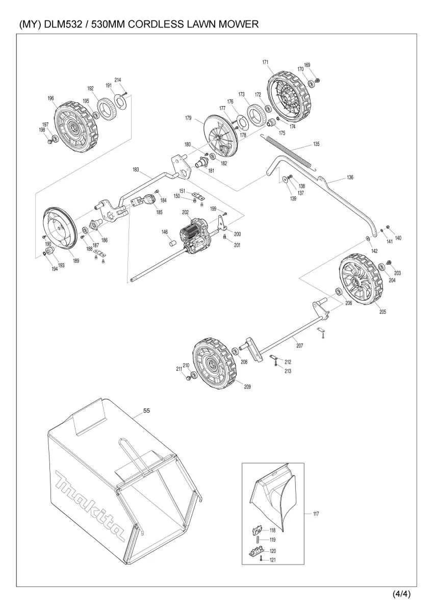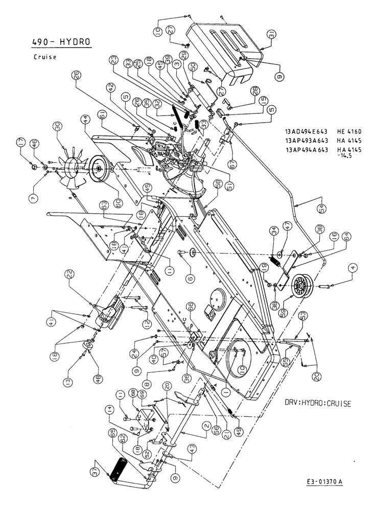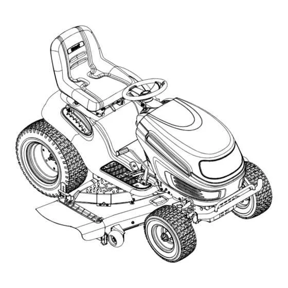
If you are aiming to optimize the performance of your garden machinery, understanding the key elements and their configuration is essential. Thoroughly familiarize yourself with the intricate layout of your equipment to ensure smoother operation and more efficient repairs.
Identifying key mechanical parts and understanding their interactions within the machine allows for quicker troubleshooting and more accurate replacements. Each piece has a designated role, contributing to the overall efficiency. Knowing the most common issues with specific components can save valuable time when performing maintenance or repairs.
Refer to detailed technical layouts for a precise understanding of where each component fits. These layouts give insight into the operational flow and highlight potential problem areas in need of immediate attention. Proper examination of these guides will reduce the risk of overlooking smaller yet critical parts, which could lead to system malfunctions if neglected.
Ensure to regularly clean and inspect the mechanical sections, as dirt and wear are often the culprits behind reduced performance. Proper lubrication and timely replacement of worn-out pieces are key to maintaining optimal functionality.
Understanding the Components of Your Grass Cutting Machine
Identify key components such as the engine, blade, and drive system for efficient operation. The engine, often located at the rear, powers the entire mechanism, while the blade assembly ensures a clean cut. The transmission or drive system, which includes wheels and axles, controls movement speed and ease of handling.
Ensure proper maintenance by inspecting the cutting blade for damage or wear. Replace or sharpen as necessary for optimal performance. The fuel system, including the tank and carburetor, should be regularly cleaned to prevent clogs and ensure smooth operation.
Check the air filter for any blockages. A clogged filter will reduce engine efficiency and may lead to overheating. Likewise, inspect the belt for wear. A frayed or broken belt may cause the machine to lose power or become unresponsive.
Familiarize yourself with the control levers and switches for easy start-up and operation. Pay close attention to the throttle and brake systems, which are critical for maintaining proper speed and stopping when needed.
For safety, always turn off the engine before performing any maintenance or adjustments. Regularly lubricate moving parts like the wheels, axles, and the blade assembly to ensure smooth movement and extend the lifespan of the equipment.
Identifying Key Components in the Diagram

To accurately identify critical elements in the visual schematic, focus on the following key areas:
- Engine Housing: The central unit that houses the motor. Look for a large, enclosed section, often represented with detailed outlines to indicate its size and shape.
- Blades: These are typically positioned at the bottom and are depicted with sharp lines or edges. In some diagrams, you may notice rotation arrows indicating their movement.
- Fuel Tank: This component is usually highlighted with a distinct shape, often a rounded or cylindrical container, located near the engine.
- Wheels: Look for the circular elements positioned at the corners. They may be represented with hubs or axles connected to the chassis.
- Handlebars: Often shown as two parallel, straight lines extending from the body, typically with grips at the top. Pay attention to their attachment points to the main frame.
- Exhaust System: Typically marked with a vent or pipe extending from the engine area, this part may be smaller but crucial for venting gases.
- Drive Mechanism: Look for gears or belts, often shown connecting the motor to the wheels. These can help distinguish manual from self-propelled models.
Examine the connections between these components carefully, as they will often indicate how the system functions as a whole. These parts are the backbone of the schematic and provide a roadmap for maintenance and repairs.
How to Locate Specific Components for Replacement
Begin by checking the manual of the device for a list of essential elements and their location within the assembly. It’s crucial to identify the precise model number to ensure compatibility with replacement items. If the manual isn’t available, consult the manufacturer’s website or customer service for assistance in locating part numbers.
Next, look for online resources or platforms that specialize in repair guides. These typically offer comprehensive breakdowns of the system layout, making it easier to locate the specific piece you need. Ensure you’re looking at accurate diagrams or 3D models for clarity in identifying each segment of the mechanism.
For difficult-to-find elements, try searching by part number. Manufacturers often provide these identifiers on the component itself or in the technical specifications. Once you have the part number, it can be cross-referenced with online shops or authorized distributors for quick acquisition.
If the part is broken or malfunctioning, examine it closely for any numbers or identification codes. These are usually stamped or printed on the surface. Using these identifiers in combination with online resources can significantly reduce the time spent searching for the correct replacement.
Pro Tip: Use specific keywords and avoid generic terms when searching online for a more targeted result. For example, input exact names or codes rather than vague descriptors like “gear” or “handle.”
Understanding Part Functions and Compatibility

For optimal performance, it’s crucial to identify the specific role each component plays in the assembly. For example, the engine drive system is essential for providing the motion needed to propel the machine, while the cutting blades ensure precision in grass trimming.
Always verify part compatibility by cross-referencing model numbers. The drive belt from one model may not fit others due to varying pulley systems, and using the wrong size can result in ineffective operation or damage. For blades, check both the length and mounting holes–these need to align precisely to maintain cutting efficiency and safety.
If replacing components, opt for original manufacturer parts or reputable aftermarket options that specify model compatibility. Using a non-matching spindle assembly could lead to improper rotation, causing uneven cuts or mechanical strain.
Regularly consult the manufacturer’s manual or parts catalog to ensure that each replacement part is specifically designed for your unit’s needs. Compatibility isn’t just about fitting–it’s about maintaining efficiency and safety in operation.