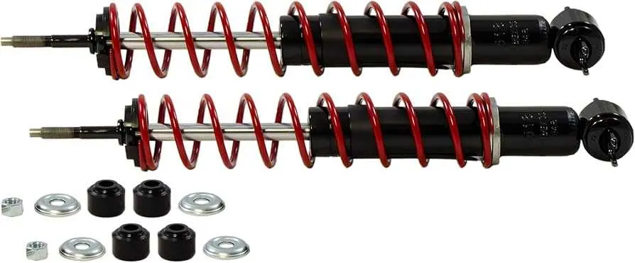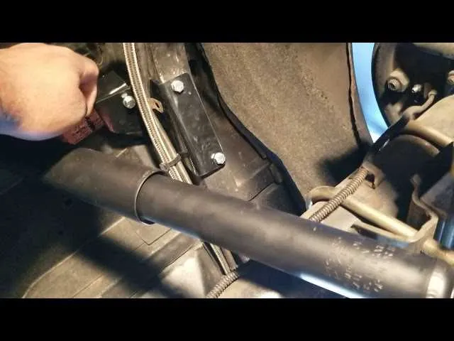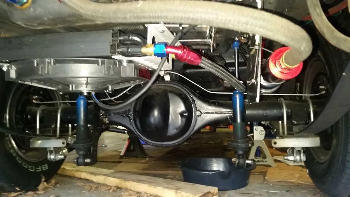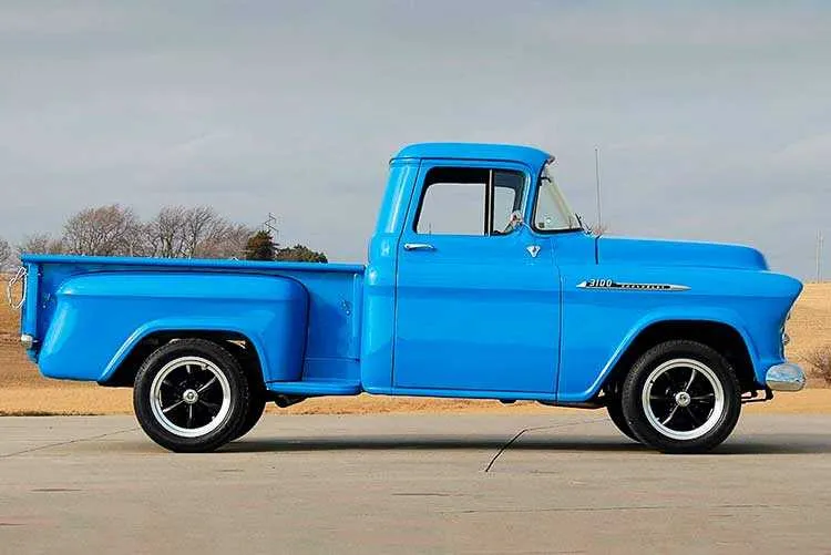
For optimal suspension performance on your vintage vehicle, correctly positioning the suspension components is crucial. When working on the 1968-1972 model years, ensuring accurate attachment points for the rear suspension elements will provide enhanced handling and ride quality. Follow the specifications closely to maintain alignment and prevent future mechanical issues.
Measure carefully to determine the exact location for the shock absorber brackets. The precise spacing between the axle and frame is key to maintaining the vehicle’s balance. Verify the distances at multiple points to avoid inconsistencies. This will ensure that the system absorbs impacts without strain or misalignment.
Mark your installation points based on factory recommendations, and use high-quality tools for cutting and securing components. Take extra care with the angle and torque when securing the brackets, as these adjustments directly affect the suspension’s efficiency and the overall driving experience.
Always double-check all connections before reassembling. A minor misalignment could lead to premature wear or reduced stability. With proper installation, you’ll restore the suspension to its full functionality, ensuring a smooth, responsive ride for years to come.
68-72 Chevy Nova Rear Shock Mount Placement Diagram: A Practical Guide

To achieve proper suspension performance on a 1968-1972 model, begin by marking the correct points for installing the suspension strut brackets. These are essential for ensuring correct alignment and preventing wear. Start by locating the lower control arm and measuring approximately 12 inches from the axle centerline towards the frame. This area is where the mounting bracket should be welded for optimal stability.
Next, check the frame’s rear section. The mounting plate should be positioned just below the upper suspension arm, with precise alignment along the frame’s inner edge. Ensure a 4-inch gap between the bracket’s bottom edge and the axle’s upper point. This spacing allows for smooth travel and avoids interference during suspension movement.
When installing the plates, use high-quality welding to ensure durability and prevent any loosening. Consider reinforcing the area with additional support if the vehicle will be subjected to heavy-duty use or modifications. Double-check that both sides are symmetrically aligned to avoid uneven performance.
For a seamless setup, also inspect the length of the upper and lower components. Aim for a balance that ensures consistent force distribution across the suspension system. Once mounted, verify that all angles are correct, particularly the angle of attack, which should be slightly inclined to avoid excessive stress on the frame over time.
Finally, after installing, test the suspension system by performing a series of test drives, checking for any signs of misalignment or instability. Make adjustments as necessary to guarantee smooth handling and ensure the vehicle’s safety on the road.
Accurate Location of Suspension Component Anchors for 1968-1972 Models
For optimal performance and alignment, it is crucial to position the suspension component anchors correctly. The exact location for these anchors on 1968-1972 vehicles requires precision to maintain handling stability and ensure compatibility with other suspension parts.
- Ensure the anchor points align with factory measurements for consistent ride quality.
- Typically, the mounting points are positioned near the frame’s rear section, just behind the axle assembly.
- Verify the distance between the anchor and axle centerline is approximately 12 inches for a balanced setup.
Mark the anchor location using a measuring tape and level to guarantee symmetry on both sides. The vertical alignment should maintain a slight angle for effective load transfer, ideally around 15 degrees relative to the horizontal axis.
Consider using original or reproduction hardware to maintain integrity and prevent long-term issues. Custom brackets may be necessary if any modifications to the frame have been made.
- Measure from the axle centerline to the intended location.
- Use a plumb line to check the vertical orientation of the anchor site.
- Drill carefully to avoid compromising frame strength.
Double-check your measurements before securing the components to avoid misalignment, which can lead to poor handling and increased wear on the suspension system.
Step-by-Step Instructions for Installing Rear Shock Mounts on 68-72 Chevy Nova

1. Prepare the workspace: Lift the vehicle using a hydraulic jack and secure it with jack stands. Ensure the car is level for precise installation. Remove the wheels to access the suspension components more easily.
2. Locate the installation points: Identify the locations where the mounting points are positioned on the frame. Use a flashlight to clearly see the area, and make sure there’s no rust or debris that could affect the process.
3. Remove old components: If you’re replacing old mounts, start by unscrewing the bolts holding the existing setup in place. Use penetrating oil on the bolts if they’re rusted or difficult to remove. Keep these bolts for reference if you’re using aftermarket components.
4. Align the new components: Position the new mounts at the identified points. Ensure that the mounting holes line up properly with the vehicle’s frame and suspension parts. Use a jack to slightly lift the suspension if necessary for better alignment.
5. Secure with bolts: Insert the mounting bolts through the holes and tighten them with a torque wrench to the manufacturer’s recommended specifications. Avoid over-tightening, which could cause damage to the frame or new parts.
6. Double-check alignment: After tightening, verify that the components are securely in place and that there’s no play. Make sure everything is aligned symmetrically for consistent performance.
7. Reassemble the suspension: Reattach any suspension components or hardware that were removed during the installation. Carefully reassemble the parts in reverse order of removal, ensuring all bolts are torqued to the proper settings.
8. Test the installation: Lower the vehicle and test the suspension system. Perform a short test drive to ensure everything functions correctly. If any noises or issues arise, inspect the installation points again for proper tightening.
Common Issues and Troubleshooting Suspension Component Alignment on 68-72 Chevy Models

Ensure the upper bracket aligns precisely with the frame when securing suspension components. Misalignment can cause excessive wear and poor handling performance. Check that the bolt holes are not deformed or too wide, as this compromises structural integrity. A common issue is the loosening of hardware over time, which can lead to squeaks or rattles. Tighten all fasteners to manufacturer specifications and use quality locking nuts to prevent further issues.
Inspect for any cracks or stress points around the mounting area. These can occur due to improper torque or excessive force during installation. If damage is found, reinforce the area or replace the affected components. It’s critical to replace worn-out bushings immediately to avoid unnecessary wear on surrounding suspension parts.
Verify that all mounting surfaces are clean and free of debris. Any foreign material can affect the fitment and cause instability. Use a wire brush or sandpaper to ensure a smooth, clean surface before installing new components. Additionally, ensure that the suspension components are symmetrical to avoid uneven load distribution that could cause handling issues.
Another common problem arises from improper installation angles. When components are installed at the wrong angle, it can lead to uneven stress on the suspension system, reducing performance and increasing wear. Double-check the angle using an alignment tool to ensure everything is set within the proper range.
If issues persist, inspect the subframe for rust or deformation, which can alter the original positioning of the assembly. Reinforcing or replacing the subframe may be necessary for achieving correct alignment and optimal performance.