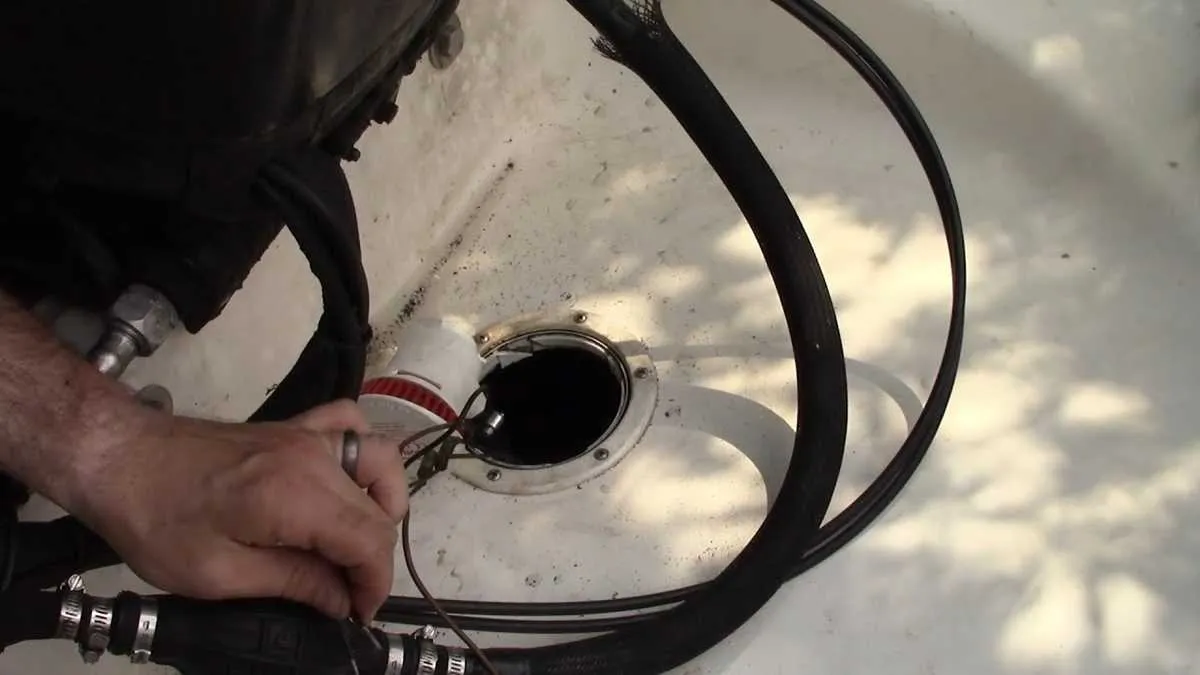
To ensure optimal performance and safety when setting up a water removal unit on a vessel, it is crucial to adhere to a precise electrical configuration. First, connect the unit’s terminal to the designated power source, ensuring a solid and secure connection. It’s recommended to use marine-grade wiring to prevent corrosion and ensure longevity of the setup.
For controlling the system, install a manual switch or a float switch for automatic activation based on water levels. Make sure to wire the float switch according to the manufacturer’s specifications to avoid any malfunctioning or inadvertent operation. Always use a fuse or circuit breaker rated for the device to protect the system from electrical surges.
When routing the wiring, ensure that all connections are made in waterproof enclosures to prevent moisture exposure. Check the integrity of each connection regularly and replace any corroded components promptly to maintain the reliability of the setup. Also, double-check the polarity of the electrical leads before making final connections to avoid damaging the equipment.
In systems where multiple units are used, always follow the recommended guidelines for parallel connections to distribute power evenly across all devices. This not only enhances efficiency but also prevents overloading the circuit.
Electrical Configuration for Marine Water Removal System
Ensure the motor is connected to a reliable power source with proper fusing. The negative terminal should be grounded securely to the hull or another solid ground point. For optimal performance, the control switch should be installed in an easily accessible location near the helm. Use waterproof connectors to avoid corrosion, and route cables through protective conduit to shield them from environmental damage.
Make sure the power cable has a sufficient gauge to handle the current draw without excessive voltage drop, typically 12 AWG or thicker, depending on the length of the run. For enhanced safety, integrate a manual override to allow operation in case of an automatic system failure. Additionally, check that all connections are tightly secured and free of any rust or oxidation, which could affect the circuit’s reliability.
The system’s switch should be rated for marine environments, with an IP67 or higher waterproof rating. Consider using a relay if your setup involves higher amperage to prevent the switch from overloading. Verify that all components meet marine standards to withstand the saltwater environment, ensuring longevity and consistent functionality of the unit.
Understanding the Basic Wiring Setup for Searay Bilge Pumps
To ensure proper installation, start by connecting the negative terminal of the device to the boat’s ground system. This provides a stable return path for the electrical current. Next, link the positive wire to a dedicated fuse block, ensuring that the fuse rating matches the amperage of the device to protect against overloads.
For the switch, a low-voltage, sealed toggle switch is recommended. Install it in an accessible location, ensuring it remains waterproof. Connect one side of the switch to the positive lead from the power source and the other to the positive input of the motor, enabling control from the cabin or helm.
Use marine-grade cables, rated for saltwater exposure, to minimize corrosion. When routing the wiring, avoid sharp bends and ensure that the cables are securely fastened to prevent chafing or accidental disconnections during operation.
Finally, check the system by manually triggering the switch to verify that power is properly supplied to the motor. Ensure that the fuse blows only if there is an overload, not under normal operating conditions.
Step-by-Step Guide to Installing the Pump Electrical System

Start by ensuring that the power source is disconnected before working on the electrical setup. Begin by selecting the correct gauge of wire based on the amperage requirements of the system. Typically, a 14 AWG wire is suitable for most small to medium-sized units. Ensure the wire length is sufficient to connect the components without unnecessary slack.
Next, install a suitable fuse near the power source to protect the circuit. The fuse should be rated slightly higher than the unit’s maximum current draw, but not too high to prevent damage in case of a short circuit. Use a waterproof fuse holder for added durability in a marine environment.
Attach the positive wire from the power source to the input terminal of the device. Secure the connection with a terminal ring to prevent any loose connections. Ensure that the wire is routed in a way that avoids any sharp edges or areas that could cause abrasion over time.
Now, connect the negative wire from the device to a common ground point on the vessel, preferably a designated ground bus bar. This ensures the electrical system is properly grounded, reducing the risk of electrical interference or system malfunctions.
If installing an automatic activation switch, position it near the lowest point of the hull where water would naturally accumulate. Connect the activation switch between the power source and the device. This switch will allow the system to turn on automatically when water is detected.
Finally, test the system to ensure proper operation. Turn on the power and check for any unusual noises or vibrations. Verify that the unit activates and deactivates as expected, both manually and automatically. Secure all wiring with zip ties or cable clips to prevent movement or contact with any moving parts.
Common Issues and Troubleshooting Tips for Boat Pump Electrical Connections

Ensure that the fuse is in good condition and matches the specifications for your system. A blown fuse is a common issue that causes the pump to stop working. If the fuse is intact, check the wiring for signs of wear, fraying, or corrosion, especially around the connections.
- Connection Problems: Loose or corroded terminals can cause intermittent operation or a complete failure. Clean the terminals and secure all connections tightly.
- Overheating: If the system overheats, inspect the circuit for any faulty connections or short circuits. Ensure the motor is not drawing excessive current, which could indicate an underlying electrical issue.
- Power Supply Issues: Verify that the battery voltage is sufficient and consistent. A low or unstable voltage supply may prevent the system from operating correctly.
Test the electrical components with a multimeter. Begin by checking for voltage at the terminals. If there is no voltage, trace the circuit to find the source of the issue, starting from the power source and moving toward the motor.
- Inspect the fuse and replace it if necessary.
- Test the relay to ensure it functions properly, as a malfunctioning relay can prevent the system from receiving power.
- Look for any exposed or damaged wiring that could be causing shorts or loss of power.
For systems with multiple components, use a wiring diagram to check each part of the circuit and ensure that all elements are connected as intended. If the motor runs but the system still doesn’t operate as expected, check the float switch for blockages or malfunction.