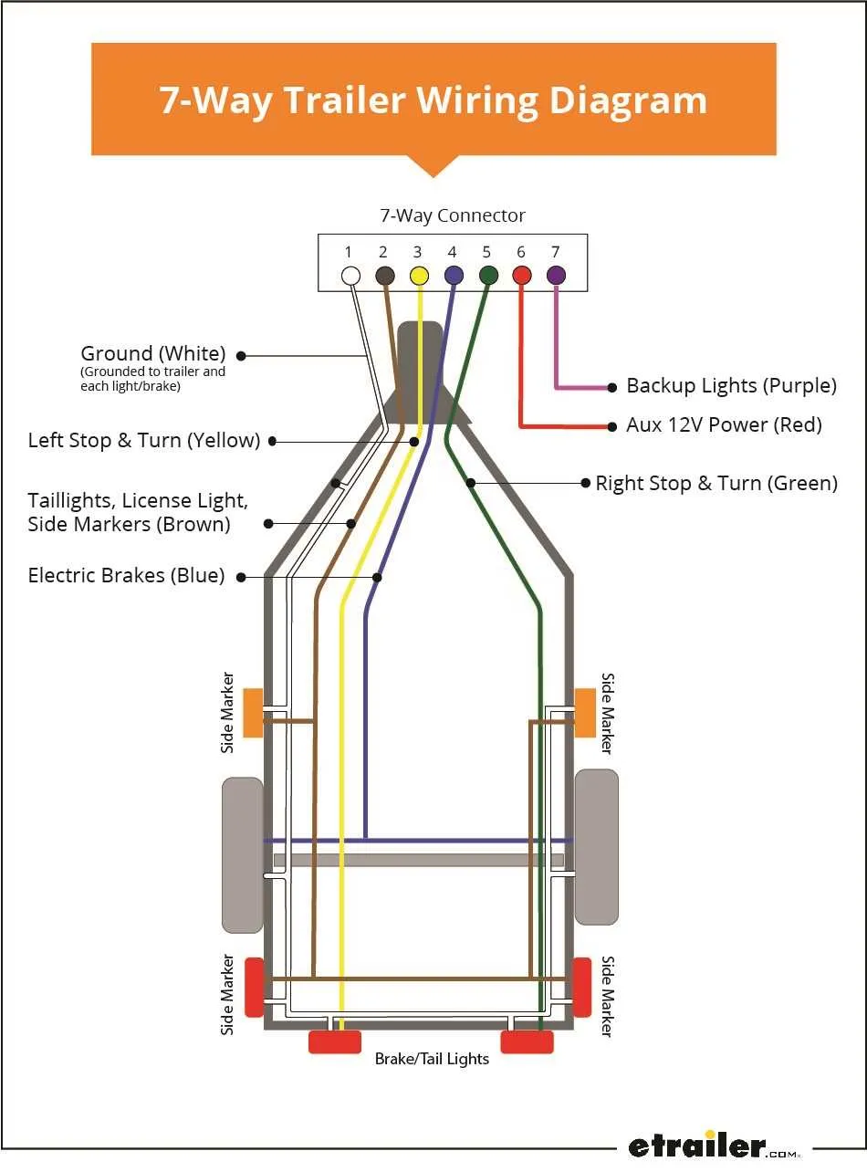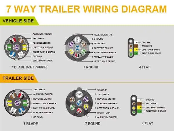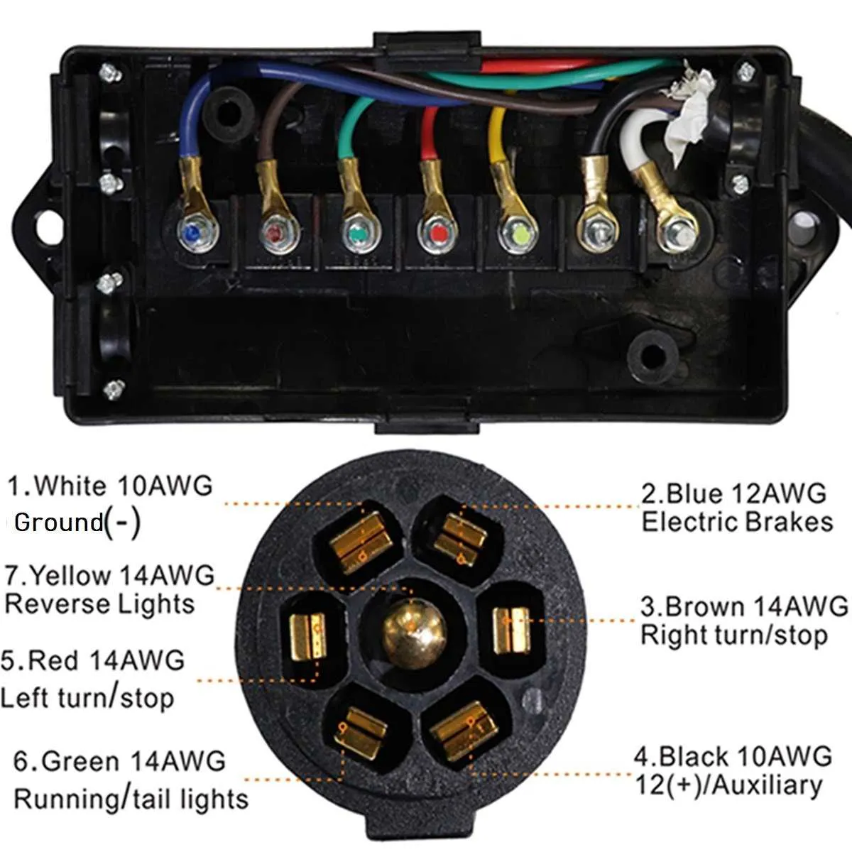
When connecting a vehicle to a trailer, ensuring a proper electrical connection is crucial. A 7-pin setup is commonly used to facilitate a range of functions, from lighting to brake signals, providing a more versatile and reliable link. Each pin serves a specific purpose, and understanding its function can prevent costly mistakes during setup.
The configuration typically includes connections for the vehicle’s tail lights, turn signals, brake lights, reverse lights, and a ground wire. It’s important to use the right type of connector for your specific vehicle and trailer type to ensure compatibility. Following the correct sequence and pin-out arrangement is essential for optimal performance.
To make the installation easier, always double-check the color-coding of wires and verify that each pin is correctly connected. Having a detailed schematic at hand can help you avoid confusion when connecting the components. Keep in mind that some connectors may also provide additional pins for auxiliary functions, such as electric brakes or power supply.
Once installed, always test the system to ensure proper operation. This includes checking lights, signals, and any other connected features to confirm everything is functioning as expected. The reliability of your connection directly impacts the safety of your towing setup.
7-Pin Connector Wiring Guide

For optimal functionality when connecting your vehicle to a 7-pin electrical system, ensure the following connections are made correctly:
1. The first pin (usually on the top left) should be linked to the ground wire, which is essential for completing the circuit.
2. The second pin is designated for the tail light circuit, responsible for illuminating the rear lights of the connected unit.
3. The third pin is used for brake lights; connect it to the vehicle’s braking system to activate the brake signals.
4. The fourth pin controls turn signals. Proper connection ensures that the left and right signals on the unit will activate when the respective vehicle signals are turned on.
5. The fifth pin is for reverse lights. It is important for visibility when reversing, making it an essential part of the setup.
6. The sixth pin provides a 12V auxiliary power source. This is often used to charge batteries or power additional accessories during travel.
7. The seventh pin is reserved for electric brake control. It connects to the braking mechanism of the unit, allowing you to manage the brakes from the vehicle.
Check the pin positions carefully to avoid any misconnection that could disrupt the electrical functions, leading to safety risks or damage to your equipment. Use a voltage tester to confirm each wire is properly connected.
Understanding the Pin Configuration and Purpose of Each Connection
Each pin in a 7-pin connector serves a specific purpose that ensures proper functioning of electrical components. Below is a breakdown of the connection layout and the role of each pin:
1. White – Ground: The ground connection is crucial for completing the electrical circuit. It connects the towing vehicle’s and the towed unit’s ground, preventing electrical faults and ensuring safety.
2. Brown – Tail Lights: This pin is dedicated to controlling the rear lights. It provides power to the tail lights, ensuring they function properly during driving or when parked.
3. Green – Right Turn Signal and Brake Light: Used for the right turn signal and brake light, this pin enables visibility for other drivers when turning or braking on the right side of the vehicle.
4. Yellow – Left Turn Signal and Brake Light: This connection is responsible for the left turn signal and brake light, allowing others to recognize when the left side is signaling or stopping.
5. Red – Electric Brakes: This pin powers the electric brake system. It allows the towing vehicle to send signals to activate the brakes on the towed unit, ensuring synchronized stopping.
6. Blue – Reverse Lights: For activating the reverse lights on the towed vehicle, this pin is activated when the vehicle shifts into reverse gear, improving visibility when backing up.
7. Black – 12V Power: Provides a constant 12V power source for accessories on the towed unit, such as interior lights or battery charging systems, ensuring that the towed unit has sufficient power when in use.
Correctly identifying and connecting these pins is essential for optimal performance and safety when operating the equipment.
How to Install a 7-Pin Connector on Your Vehicle

To begin the installation of a 7-pin connector, ensure you have the proper kit with the necessary tools, such as a socket wrench, wire stripper, electrical tape, and the connector itself. Follow these steps:
- Locate the connection point: Find the designated spot on your vehicle where the electrical harness is to be connected. Usually, it is near the bumper or rear frame.
- Prepare the wires: Strip the insulation from the ends of the wires that will be connected to the pins. You should have at least seven separate wires, each corresponding to a specific function.
- Connect the ground wire: The ground wire is usually the white one. Attach it to a clean metal surface on the vehicle’s frame. Ensure the connection is tight and free of corrosion.
- Attach the power wire: The wire for supplying 12V power (typically blue or black) should be connected to the appropriate terminal in the connector.
- Connect the brake light wire: The wire for brake lights (usually red or yellow) should be secured to its respective pin on the connector.
- Wire the turn signals: Connect the left and right turn signal wires (often green and yellow) to the corresponding terminals.
- Test the connections: Before finalizing the installation, test each pin’s functionality by activating the corresponding vehicle functions (lights, signals, etc.).
- Seal and protect the connections: Use electrical tape or heat shrink tubing to protect the exposed wires from moisture and wear.
- Mount the connector: Secure the connector to the vehicle’s rear bumper or frame. Ensure it is fastened firmly and positioned for easy access.
After installation, double-check all connections for stability. Regularly inspect the connector for wear or corrosion to maintain reliable performance. Make sure the wires are routed away from any sharp edges or moving parts.
Common Issues and Troubleshooting Tips for 7-Pin Connectors
If you experience intermittent signal loss or malfunctioning lights, begin by checking for loose or corroded connections. A poor contact can cause unreliable performance, particularly in the ground pin. Ensure all terminals are tightly secured and free from oxidation or rust, which can disrupt the flow of current.
Test each connection individually using a multimeter. Start with the ground terminal, then proceed to the individual circuits for brake lights, turn signals, and tail lights. If any circuit shows no continuity, check for breaks in the wires or a faulty connection at either the plug or vehicle-side socket.
Dirty or damaged connectors are another common issue. Clean the pins and ensure they’re not bent or broken. If the socket is worn or cracked, it might be necessary to replace the entire connector. Make sure to apply dielectric grease to prevent moisture buildup and corrosion over time.
If the brake lights or turn signals don’t work, verify the integrity of the fuse in your vehicle’s electrical system. A blown fuse could affect multiple circuits and might be the cause of the malfunction. Additionally, check for any shorts that could cause voltage loss or circuit overload.
In cases of fluctuating power or dim lighting, a voltage drop could be responsible. This is often caused by a poor ground connection or inadequate power delivery from the vehicle. Check the battery and charging system of the towing vehicle, as well as all ground straps, for any signs of wear or loose connections.
Lastly, improper pin alignment can result in inconsistent behavior. If the connector doesn’t sit properly or isn’t fully inserted, the signals may not function as expected. Always ensure the plug is fully engaged, and verify that the pins align correctly between the vehicle and the connector.