When installing and maintaining a fire suppression control unit, ensure all connections align with the prescribed layout for reliable performance. First, focus on the correct integration of the activation circuit, which serves as the central communication link for initiating fire suppression. Pay attention to the specific terminals designed to receive voltage signals, which should be carefully checked for secure contacts to avoid failures during an emergency.
Always prioritize safety measures when handling these components, as miswiring could lead to malfunctions that compromise the entire emergency response. If in doubt, consult the manual for each component, as it typically includes a schematic showing terminal connections, fuse ratings, and wire gauges. Proper identification of each wire’s function–whether for power supply, control, or communication–is crucial.
Ensure all grounding procedures are rigorously followed, as improper grounding could lead to electrical surges, potentially triggering false alarms or damaging sensitive equipment. Using color-coded wires or proper labeling of each connection can also significantly reduce the risk of incorrect installation and make future troubleshooting easier.
Finally, once installed, test the entire setup to confirm that each segment responds as expected. Testing ensures that all components, from manual overrides to automatic sensors, are properly linked and functional.
Essential Connections and Layout

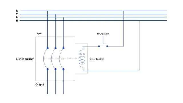
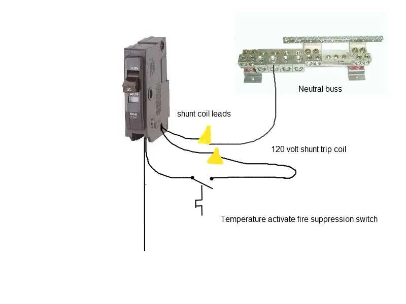
Ensure all components are properly connected according to their designated terminals. For accurate functionality, each sensor must be wired to the control unit’s input channels. Connect the actuator circuits securely to the main power supply, following the manufacturer’s voltage specifications to prevent system failure.
Important: Always adhere to the specific order of connections as detailed in the equipment’s guide. The communication links between the trigger mechanism and the control board must be tested after installation to guarantee seamless activation when necessary.
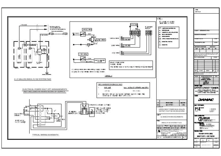
Place each relay and circuit breaker in the designated slots, ensuring that no excess wiring is present. Double-check all grounds to prevent electrical feedback or malfunction. For maintenance, document the exact configuration of each unit to streamline future troubleshooting and repairs.
Use only shielded cables to minimize signal interference, and make sure the wiring is routed away from high-heat or moisture-prone areas to ensure longevity and reliable performance. Secure all connections with appropriate fasteners to prevent loosening over time.
Tip: During installation, it’s crucial to test the sequence of operations at each stage, starting from the initial trigger point through to the final discharge process, verifying that all components interact as intended.
Identifying Key Components in the Electrical Layout

To successfully navigate the layout, focus on isolating the control panel, actuator mechanisms, and the detection devices. The control panel typically serves as the brain of the setup, where signals are received and processed. Make sure to locate the input/output terminals to trace the connections between components. The actuators, often solenoids or relays, are responsible for triggering the release mechanisms and should be clearly identified, ensuring proper connection to the control unit. The sensors play a crucial role in detecting changes in the environment, so their location and wiring path are essential for accurate functioning. Always double-check the interconnection points for continuity and ensure that they are free from any damage or corrosion that might impede functionality.
Connecting Fire Suppression Equipment to Control Panels

Ensure that each connection between the suppression unit and the control unit is made with high-quality, fire-resistant cables. Follow these guidelines for a secure and reliable setup:
- Use cables that meet the required industry standards for durability and safety.
- Securely fasten all terminals to prevent accidental disconnection or short-circuits.
- Clearly label each wire at both ends for easier troubleshooting and maintenance.
- Ensure that the control panel is properly grounded before making any connections to avoid electrical interference.
- Follow the manufacturer’s instructions regarding the placement of the connection terminals to prevent incorrect installation.
During installation, pay close attention to the polarity of the connections. Incorrect polarity can lead to malfunction or failure of the entire setup. Always cross-check with the control panel’s manual for specific wiring details.
For communication between the detection unit and the suppression mechanism, use shielded cables to avoid electrical noise. These cables help maintain signal integrity in environments prone to high interference.
When testing, simulate various fault conditions, such as power interruptions or signal loss, to ensure the connections can withstand real-world situations. Ensure the control unit responds correctly when the suppression circuit is activated.
- Verify each terminal is tightly connected with no exposed copper wire.
- Use connectors with proper insulation ratings for each voltage level.
- Conduct continuity checks after every installation phase.
Safety Protocols for Installation and Maintenance
Ensure power is disconnected before starting any installation or servicing to prevent electrical shocks. Always use a lockout/tagout procedure when disconnecting the energy source.
Wear appropriate personal protective equipment (PPE) such as insulated gloves, safety glasses, and flame-resistant clothing to minimize risks during the work process.
Before making connections, verify that all components are properly rated for the required current and voltage levels. Consult manuals and datasheets for accurate specifications.
Use color-coded conductors to clearly identify different circuits. This aids in reducing errors during troubleshooting or future maintenance.
Test all connections with a multimeter to ensure there are no short circuits or improper connections before reactivating the power supply.
Ensure that any exposed conductive parts are properly insulated or shielded to avoid accidental contact during operation.
Perform regular visual inspections of connections and components. Look for signs of wear, corrosion, or overheating, which can be indicators of potential hazards.
Follow the manufacturer’s guidelines when installing or replacing parts. Non-compliance can lead to malfunction or unsafe conditions.
During maintenance, always discharge capacitors safely to prevent electric shock risks. Keep capacitors disconnected until they are verified as safe.
Maintain clear documentation of all installations and repairs. This ensures easy access to historical data for future troubleshooting or upgrades.