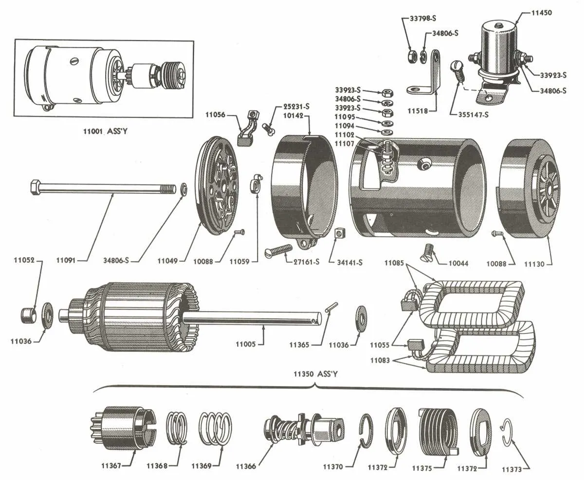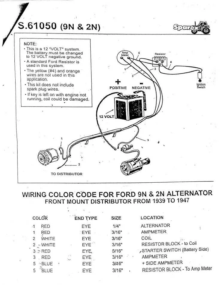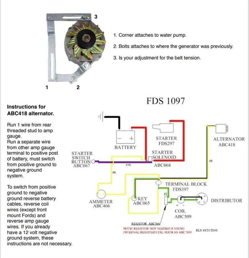
Ensure correct identification of each terminal before starting any repair or installation. The ignition switch, starter solenoid, and generator require precise linking to avoid damage or malfunction.
Battery cables must be securely attached to the designated posts, with attention to polarity to prevent short circuits. Use factory color codes to trace each conductor and confirm continuity.
For optimal performance, replace any corroded connectors and verify grounding points on the chassis. Following accurate schematics will streamline troubleshooting and prevent electrical failures in this vintage machine.
Electrical Schematic of 8N Model

To correctly connect the electrical system of the 8N model, start by identifying the main battery terminals: positive leads should connect directly to the starter solenoid, while the negative must be grounded to the chassis. Ensure the ignition switch wiring matches the factory color codes–red for power input, brown for ignition output.
Use a reliable source to cross-check the alternator connections: the field wire goes to the voltage regulator, which in turn links to the battery and ignition system. The lighting circuit requires separate leads for headlights and tail lamps; typically, blue wires serve this function. Safety switches, such as those on the clutch and brake, must be integrated to prevent accidental starts.
For the gauges and indicators panel, confirm that the oil pressure sender and temperature sensor wires run back to the dashboard connectors without splicing. Always employ proper connectors and avoid twisting wires together. Follow the original layout to maintain system reliability and prevent shorts or overloads.
Identifying Key Electrical Components and Their Functions

Start by locating the ignition switch, as it controls the main power flow and engine start sequence. The battery serves as the primary energy source, delivering voltage to all circuits. The starter solenoid acts as a relay, engaging the starter motor when the ignition is turned on.
The alternator converts mechanical energy into electrical power, maintaining battery charge during operation. Essential fuses protect individual circuits from overload, preventing damage to sensitive parts. The voltage regulator stabilizes output from the alternator, ensuring consistent current to electrical systems.
Ground connections are critical; verify their integrity to avoid erratic behavior or system failures. Key connectors include those linking the lighting system, instrument cluster, and safety switches–each ensuring proper operation and feedback.
Relays control high-current devices such as headlights and fuel pumps, triggered by low-current switches. Inspect the wiring harness for color-coded wires indicating specific circuit functions, aiding in troubleshooting and maintenance.
Step-by-step guide to tracing and repairing common electrical faults
Begin by disconnecting the battery to avoid short circuits. Use a multimeter set to continuity mode to identify breaks or shorts in the circuitry. Follow these steps carefully:
- Locate the main power feed: Identify the primary cable delivering voltage from the battery or generator to the control panel. Check for corrosion or loose connections at terminals.
- Test ground connections: Verify that all grounding points are clean, tight, and free of rust. Use the meter to ensure continuity between chassis and ground wires.
- Inspect connectors and splices: Examine each junction and plug for melted insulation, corrosion, or broken pins. Replace or reseal damaged connectors.
- Check key components individually: Measure resistance and voltage across switches, relays, and solenoids to confirm they operate within manufacturer specifications.
- Trace signal pathways: Follow each circuit segment from source to load using a wiring chart. Look for discrepancies such as unexpected resistance or open circuits.
- Repair identified faults: Cut out damaged sections of cable and replace with quality wire of matching gauge. Use soldered joints with heat-shrink tubing for durable repairs.
- Secure all lines: Ensure cables are properly clipped and routed away from heat sources and moving parts to prevent future damage.
- Test functionality after repairs: Reconnect the power source and verify each system operates correctly, monitoring for abnormal heat or intermittent failures.
Following this methodical approach ensures accurate pinpointing and effective resolution of typical electrical issues encountered in this type of machinery.
Connecting Aftermarket Electrical Accessories Without Damaging the Original Harness
Use fused add-on circuits to tap into the existing electrical system safely. Employ inline fuse holders rated appropriately for each accessory to prevent overload and potential fire hazards. Always select connection points on circuits with sufficient capacity, preferably from auxiliary or ignition-switched sources rather than constant battery feeds.
Utilize quality crimp connectors or solder joints with heat shrink tubing to ensure secure, corrosion-resistant contacts. Avoid piercing original insulation with tap connectors that can cause intermittent faults or shorts. Instead, run separate wires alongside factory bundles, securing them with zip ties to prevent movement and abrasion.
When installing relays, trigger them from low-current sources in the main harness, while routing accessory power directly from the battery with appropriate fusing. This method reduces strain on the original cables and maintains the integrity of the stock electrical paths.
Ground aftermarket devices using existing chassis grounding points or dedicated ground wires connected to clean, bare metal surfaces to avoid ground loops or voltage drops. Test all added circuits under load before finalizing the installation to verify correct operation and prevent damage.