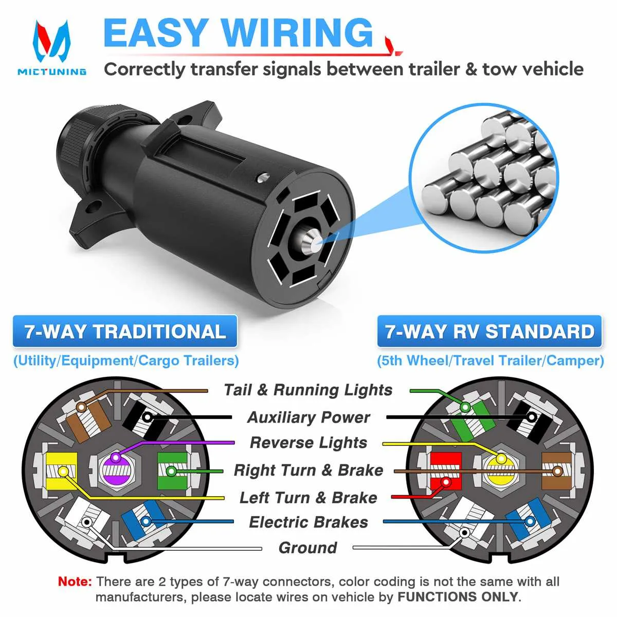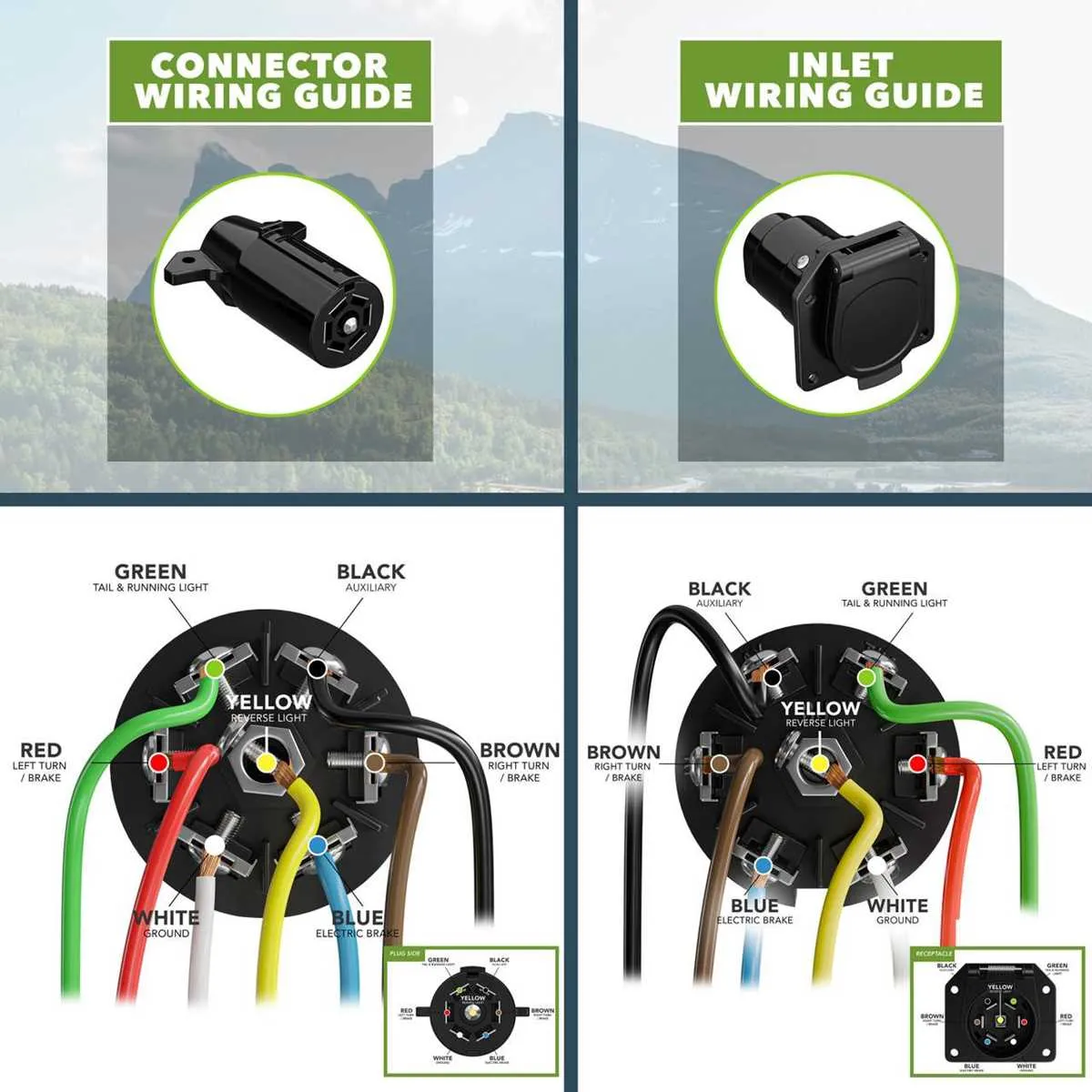
For accurate installation and troubleshooting, ensure a clear understanding of the 7-pin configuration. This setup is typically used for electrical connections in various vehicles, providing a reliable method for transmitting signals across multiple points. Each of the seven terminals plays a critical role, and recognizing the function of each pin can prevent errors and improve performance.
Start by identifying the specific connections, such as power supply, grounding, and signal paths. Pinouts often follow standard wiring practices, which are essential for maintaining compatibility across different systems. A mistake in wiring can lead to malfunctioning components or even cause permanent damage to the system.
Consult a detailed manual or schematic to get precise pin assignments for your particular use case. This allows you to match each terminal with the correct wire, ensuring proper operation. Pay special attention to the color coding and numerical sequence to avoid mix-ups, as the right configuration is crucial for safe and efficient operation.
7-Pin Connector Wiring Overview
For optimal performance, always use a color-coded wiring system to connect the pins on your 7-pin connector. Ensure that each wire is connected to the correct terminal to avoid malfunction or potential damage to your trailer or towing vehicle.
The first terminal is typically used for the ground connection. It should be securely fastened to a clean, unpainted metal surface to ensure proper grounding.
The second pin handles the tail lights. This connection allows the vehicle’s rear lights to illuminate on the trailer, providing visibility for the towing setup at night or in low-light conditions.
Pin three is for brake lights. This wire should be hooked up to the brake light circuit, ensuring that when the vehicle’s brakes are activated, the trailer’s brake lights also illuminate.
The fourth connection is for turn signals. It links to the vehicle’s left turn signal circuit, signaling direction for the trailer when turning left.
The fifth terminal is used for the right turn signal. This wire connects to the vehicle’s right turn signal circuit, providing directional indicators for the trailer.
The sixth pin controls the auxiliary power circuit. This may power additional lights or devices such as trailer-mounted brakes or air brakes, depending on your setup.
Lastly, the seventh pin is commonly used for reverse lights. It activates the reverse lights on the trailer, aiding in visibility when reversing.
Ensure that the wiring harness is securely connected and insulated, preventing any short circuits or electrical interference. Double-check each terminal before use to confirm proper installation.
Understanding the Wiring Configuration of a 7 Pin Connector
To ensure proper functionality, it is critical to adhere to the correct wiring setup when connecting a 7 pin connector. Each pin has a specific role, and a mistake in wiring can lead to malfunctioning lights or electrical systems in trailers and caravans.
Pin 1: Typically used for the left indicator. Connect the wire from the left turn signal to this terminal.
Pin 2: This terminal is reserved for the right indicator. The wire from the right turn signal should be attached here.
Pin 3: This is the ground terminal. Always connect the ground wire to this pin to complete the electrical circuit.
Pin 4: Dedicated to the left brake light. Ensure this wire comes from the brake light on the towing vehicle or trailer.
Pin 5: This is for the right brake light. It functions similarly to the left brake light, but for the right side.
Pin 6: Reserved for the auxiliary power supply, often used for powering additional systems like charging or refrigeration within a trailer.
Pin 7: This pin is typically used for the rear fog light, although the specific use may vary depending on local regulations or the vehicle’s requirements.
Properly wiring each terminal according to its purpose is essential for safe and reliable operation of all connected electrical systems. Double-check the connections to avoid electrical issues or hazards.
How to Identify Pin Functions in a 7-Pin Electrical Connector

Start by referring to the standard configuration of a 7-pin electrical connector. Each pin has a specific function. Here’s how you can identify them:
- Pin 1: Typically used for ground or chassis. It’s essential for stabilizing the entire system.
- Pin 2: Usually designated for the tail light. It provides power for the vehicle’s rear lighting system.
- Pin 3: Acts as the right turn signal. This pin ensures the right indicator works correctly.
- Pin 4: Reserved for the left turn signal. Controls the left indicator.
- Pin 5: Used for brake lights. It triggers the brake light when the brake pedal is engaged.
- Pin 6: This pin typically connects to the reverse light. It activates when reversing the vehicle.
- Pin 7: Often provides power for auxiliary functions like battery charging or trailer battery.
To confirm the function, use a multimeter to test for voltage or continuity. Ensure each pin is connected to the right circuit based on the vehicle or trailer’s requirements. Double-check that each wire color corresponds to the proper function as described in the connector’s manual.
Common Mistakes to Avoid When Installing a 7 Pin Connector
Incorrect wire color matching is one of the most frequent errors. Always refer to the manufacturer’s color-coding guide to ensure accurate connections for brake lights, reverse lights, and other functions. Miswiring can result in malfunctioning signals or damage to your vehicle’s electrical system.
Failing to check for corrosion or dirt before installation can cause poor connectivity and signal failure. Clean all contact points and ensure the connectors are free from any debris to guarantee a reliable electrical connection.
Underestimating the need for proper sealing is another mistake. Make sure the connector is weatherproofed. Any gaps or exposed wiring can lead to short circuits or rusting, especially in outdoor conditions.
Over-tightening screws can damage the housing or cause internal wiring issues. Tighten the screws securely, but stop once you feel resistance to avoid unnecessary strain on the components.
Neglecting to test all connections before finalizing the installation can lead to undetected problems. Always verify that each function works correctly, including lights, signals, and the trailer’s braking system.
Using an inappropriate tool for the task can lead to damaged connectors or improper crimps. Invest in a proper crimping tool designed for automotive use to ensure a solid, reliable connection.
Improper cable routing can result in wear and tear due to friction or excessive bending. Make sure cables are secured properly and protected from sharp edges or heat sources to prevent future issues.