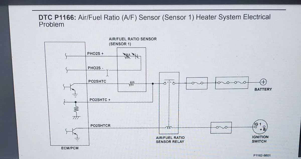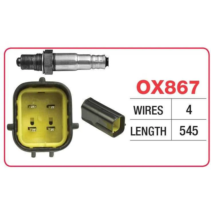
When working on the oxygen monitoring system of your vehicle, it’s crucial to understand the correct pin assignments and wiring sequence. The components responsible for measuring the oxygen levels in the exhaust gases are integral to maintaining proper engine performance and emissions control. Begin by identifying the four main wires: ground, signal output, power input, and heater control. Each plays a distinct role in ensuring accurate readings and system efficiency.
Start by connecting the ground wire to a solid chassis or engine block. The power input should be routed directly from the vehicle’s main electrical system to ensure consistent voltage levels. The signal output is what communicates the oxygen data to the vehicle’s computer, adjusting fuel ratios as necessary. Finally, the heater control wire regulates the temperature of the unit, ensuring it operates within the optimal range.
For proper functionality, ensure all connections are secure and free of corrosion. Use high-quality connectors and insulate any exposed wires to prevent shorts. Always test the system with a multimeter to confirm each connection is working as intended before final installation.
O2 Sensor Electrical Connections

Ensure proper connection of the oxygen monitor to the vehicle’s engine control unit (ECU) for accurate emissions data. Here’s a quick guide to identify and connect each lead correctly:
- Power wire – Connect to a stable 12V supply, typically from the car’s main fuse box or ECU.
- Ground wire – Attach to a solid ground point near the exhaust manifold.
- Signal wire – This carries the voltage readings back to the ECU. Ensure this lead is well-shielded to avoid interference from surrounding components.
For accurate operation, always use the manufacturer’s color code for the leads. Typically, these colors represent:
- Black – Ground
- White – Power
- Grey – Signal
Failure to adhere to these connections can cause incorrect readings, leading to poor vehicle performance and increased emissions. Always double-check continuity with a multimeter before finalizing connections.
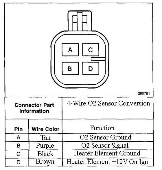
Identifying Wiring Colors and Pinouts for O2 Sensors
For precise identification, start with the color code of each wire. Typically, the black or white wire connects to the ground, while the red wire is used for the power supply. The signal wire is often gray or blue, and the heater wire may be green or brown. These color conventions, however, can vary by vehicle make and model, so always refer to the manufacturer’s guide.
Pinout configuration: The common pin arrangement for a four-wire system includes the following pins: ground (black or white), power (red), signal (blue or gray), and heating element (green or brown). It’s essential to ensure proper connections to avoid malfunction.
Tip: To confirm accuracy, use a multimeter to test each wire’s voltage and resistance. Checking the heater wire’s resistance will ensure it’s not shorted, while voltage testing can confirm proper power distribution.
Step-by-Step Guide to Connecting O2 Sensors to the ECU
Start by identifying the proper wiring channels for the oxygen monitoring device. The wires should connect the output from the measurement unit to the input terminals of the ECU. Ensure the signal wire is routed to the designated port on the ECU, often labeled as “O2” or “Lambda”.
Next, locate the power and ground wires. The power wire typically connects to the ECU’s voltage input, providing the necessary energy for the device to function. The ground wire is vital for completing the circuit and must be attached to a solid ground point on the vehicle chassis or engine block.
Secure the wiring connections with proper crimping tools to ensure a stable contact. A loose or poor connection could lead to inaccurate readings or communication failures between the device and ECU. Double-check the crimped ends for solid connection.
Ensure correct polarity when connecting. Reversed wiring could cause malfunction or even damage to the ECU. The signal output wire should be routed with care, avoiding interference from other wires or components.
Before finalizing, inspect all connections and ensure the wires are adequately insulated. Exposed wires can lead to shorts or signal degradation, affecting ECU performance.
| Wire Type | Connection Point | Function |
|---|---|---|
| Signal Wire | ECU Port (O2/Lambda) | Transfers oxygen level data |
| Power Wire | ECU Voltage Input | Provides power for operation |
| Ground Wire | Vehicle Chassis or Engine Block | Completes the circuit |
Once connected, test the system by running the vehicle and checking the ECU’s response. Monitor for any fault codes or irregularities that may indicate improper wiring. Regular inspection ensures continued accurate readings from the device, maintaining optimal engine performance.
Common Wiring Issues and How to Troubleshoot

Check for loose connections at both ends of the component cable. Ensure that all pins are securely inserted and not corroded. Corrosion is a common issue that can disrupt communication between the parts, so clean any rust or dirt with an appropriate contact cleaner.
Inspect for frayed or damaged insulation along the wire. Any exposed metal can lead to short circuits, which may cause incorrect readings or malfunction. Replace any sections that show wear to restore proper functionality.
Test continuity with a multimeter to verify the integrity of the wires. If the circuit is open, locate the break and fix it by either soldering or replacing the damaged wire. Do this step systematically to avoid overlooking any faults.
Examine the grounding connection. A poor ground can lead to fluctuating or erratic performance. Ensure that the ground is attached to a clean, unpainted surface and that the connection is tight.
Check for any signal interference or grounding issues that could be caused by nearby electrical components. Route the cables away from high-voltage sources to minimize cross-talk or electrical noise that could interfere with the data transmission.