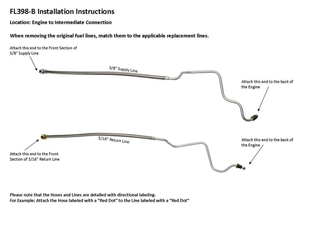
For models produced between 1973 and 1986, the primary supply conduit runs from the rear-mounted reservoir along the driver’s side frame rail, secured by metal clips approximately every 18 inches. Hard lines are typically 3/8″ in diameter, transitioning to flexible rubber hose segments at key junctions–most notably near the mechanical transfer module and the emission control units.
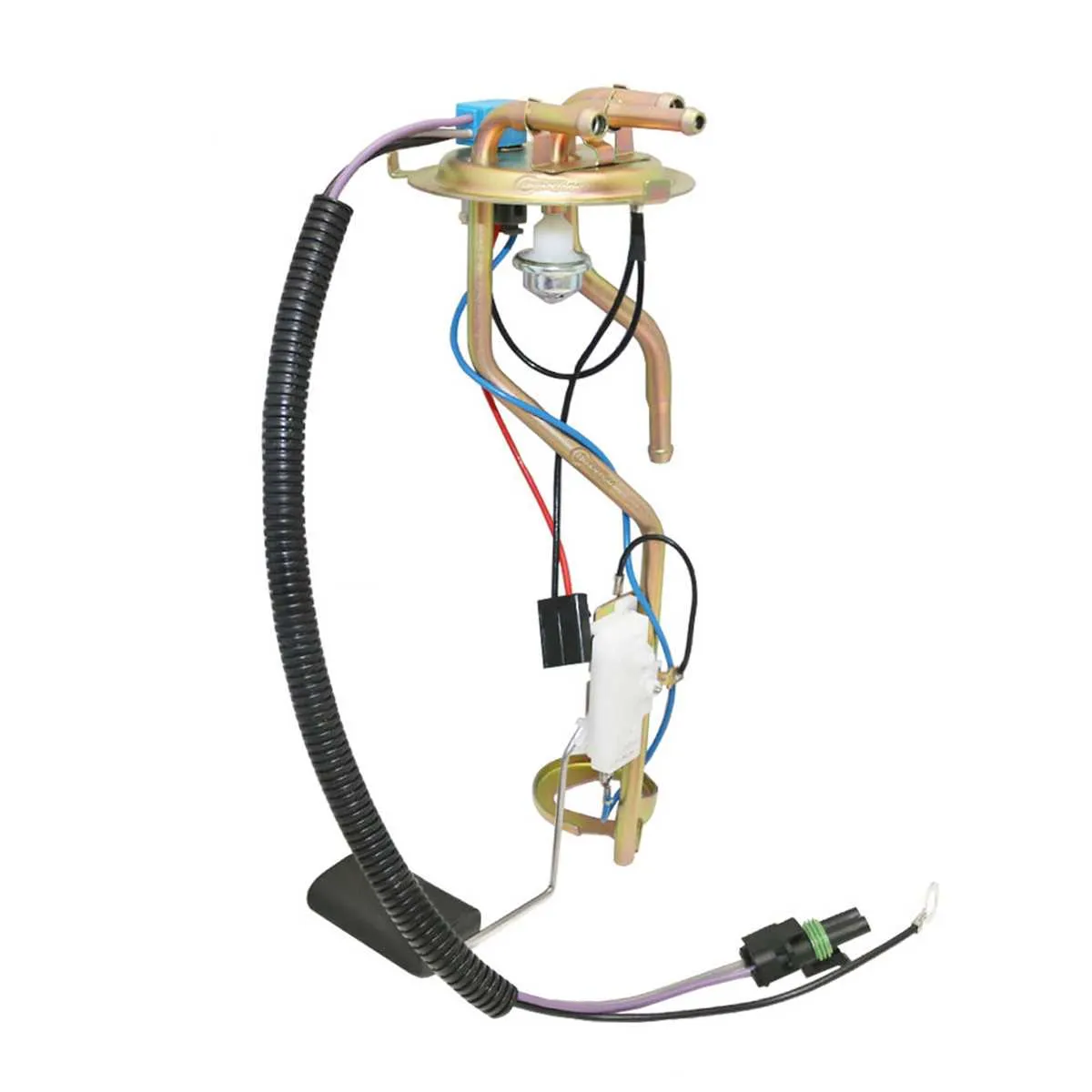
The sending unit, located at the top of the tank, incorporates a 5/16″ return path and a vapor vent. These smaller-diameter pipes often share a routing bracket with the main feed, especially in configurations equipped with dual storage cells. Always inspect Y-connectors or selector valves on dual-reservoir systems, typically mounted near the driver-side kick panel or frame rail crossover.
Ensure that all pressure lines near the carburetor or throttle body are connected using flare fittings to prevent leakage. Early versions (1973–1978) use mechanical control devices, while post-1981 layouts may incorporate electric switching modules, especially in emissions-compliant variants. Pay close attention to any rusted clips or deteriorated rubber links–they are common failure points.
Consult the factory service manual for your specific sub-model and drivetrain configuration. Variations exist depending on whether the setup includes a return system, smog control hardware, or auxiliary components like vapor separators or charcoal canisters.
Routing Overview for 1973–1986 C/K Series V8 Models

Begin at the rear sender unit located on top of the reservoir near the passenger-side frame rail. From there, a 3/8″ steel conduit runs along the inside of the chassis toward the front crossmember, secured with factory-style clips every 12 inches to prevent vibration damage.
Midway near the transmission support, the feed tube joins a rubber segment for approximately 8 inches, connecting to a metal hardline again as it reaches the mechanical pump on small-block and big-block V8s. This segment must be rated for SAE J30R9 for ethanol resistance. Return passages, typically 5/16″, follow a similar path parallel to the supply but terminate at the vapor separator canister near the engine bay’s driver-side inner fender.
On dual-reservoir configurations, a selector valve mounted beneath the cab routes pressurized content from either source. Electrical leads to the switching unit should be checked for corrosion to avoid flow disruption. Ensure all junctions use double-clamp systems or AN fittings to prevent leakage under pressure cycles.
Evaporation control includes a vent routed from the upper tank via a rollover check valve leading to a charcoal module. Blocked venting lines may cause vacuum lock during operation, especially in warmer climates. Annual inspection is essential to maintain flow efficiency and avoid cavitation near the intake module.
Fuel line routing for carbureted small-block engines (350, 305)
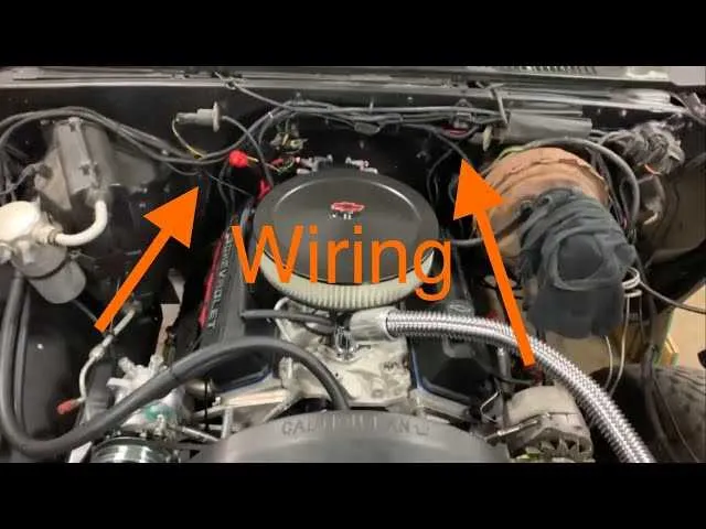
Route the primary supply hose from the rear tank outlet to a mechanical pump mounted on the lower passenger side of the engine block. Use 3/8″ steel tubing for the main segment, bending it to follow the frame rail contour and securing it with insulated clamps every 12–16 inches.
Install an inline filter between the tank and the actuator, ideally just before the pump inlet. Ensure the filter is rated for low-pressure carbureted setups (4–7 psi) and mounted vertically to prevent vapor lock.
From the pump outlet, connect a short rubber section (SAE J30R7 or better) to transition into another 3/8″ metal conduit running along the front of the block to the carburetor inlet on the passenger side. Avoid routing near exhaust manifolds; maintain at least 2 inches of clearance or use a thermal sleeve where proximity is unavoidable.
Return configuration: If equipped, route a 5/16″ return path from the regulator or carburetor return port back to the tank return fitting. Keep return bends gradual to minimize restriction and ensure smooth flow back to the reservoir.
Note: All rubber segments must be ethanol-resistant and secured with dual clamps. Do not exceed 18 inches of flexible tubing in total. Pressure readings at the carb inlet should remain between 5.5–6.5 psi for optimal operation.
Identifying Return Line and Vapor Line Connections on Dual Tank Setups
Begin by tracing the smaller diameter hoses exiting the switching valve–typically mounted along the frame rail near the selector solenoid. The return conduit is usually 1/4-inch and routes back to each reservoir, terminating near the upper portion of the sender unit flange. Confirm this path by checking for a continuous loop to both tanks without inline filters or pressure regulators.
The vapor recovery circuit connects to the EVAP canister and typically features a 3/16-inch or smaller hose. Look for a check valve or rollover valve near the tank, which prevents liquid from entering the charcoal container. This hose originates from the tank’s topmost vent nipple and does not connect to the selector valve–unlike the return system, which is routed through it.
To verify function, apply low-pressure air (under 5 psi) to suspect hoses and listen for exit points at each tank. No airflow to the EVAP canister indicates a clogged or misrouted vapor channel. Incorrectly swapped return and vent tubes may lead to poor engine operation or pressurized tanks.
Recommended materials and diameter specs for replacement fuel lines

Use 3/8-inch OD tubing for the main supply route and 5/16-inch for the return. Both sizes match factory specifications for models produced between 1973 and 1986.
- Nylon 12 (SAE J2260 Type B): Preferred for modern replacements due to flexibility, corrosion resistance, and compatibility with ethanol blends. Rated up to 200 psi.
- Bundy steel (double-walled): Original equipment type, highly durable, but prone to corrosion without proper coating. Best used with zinc or PVF plating.
- Stainless steel (304 or 316): Excellent longevity, immune to rust, ideal for high-performance builds. Requires precision bending tools.
- Rubber (SAE 30R9 or 30R14T2): Only for short sections or connections; must be EFI-rated and resistant to modern fuels. Clamps should be EFI-specific, not worm gear types.
Avoid 30R6 or 30R7 hoses, as they degrade with ethanol. Secure all routes with insulated clamps every 12–18 inches and use barbed fittings with double clamps at junctions.