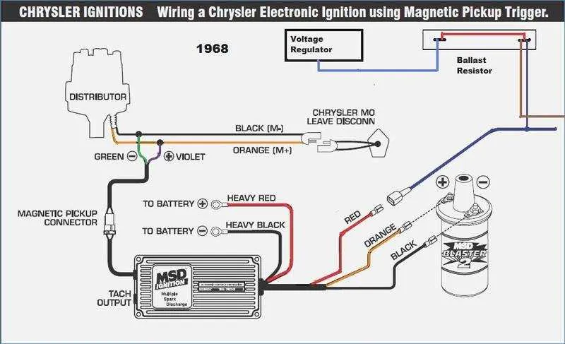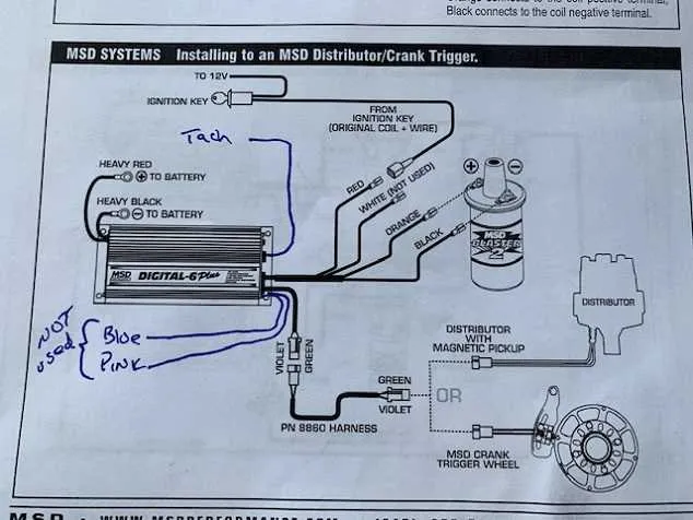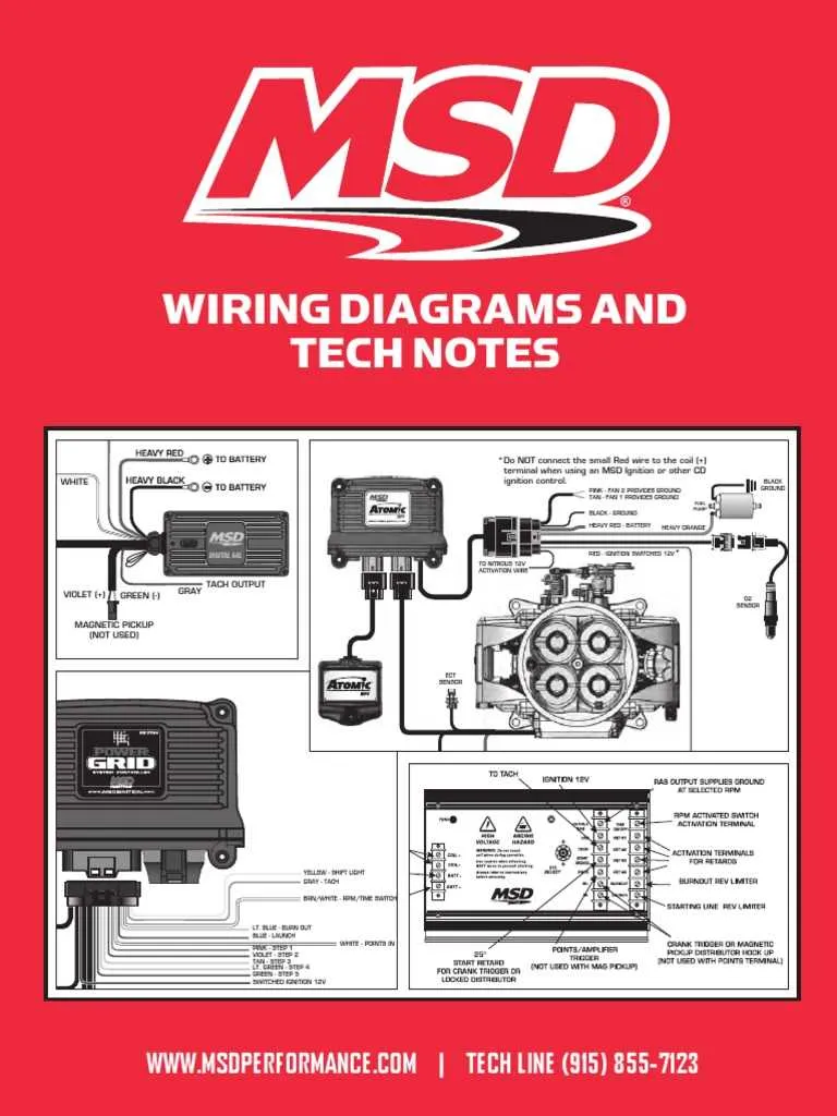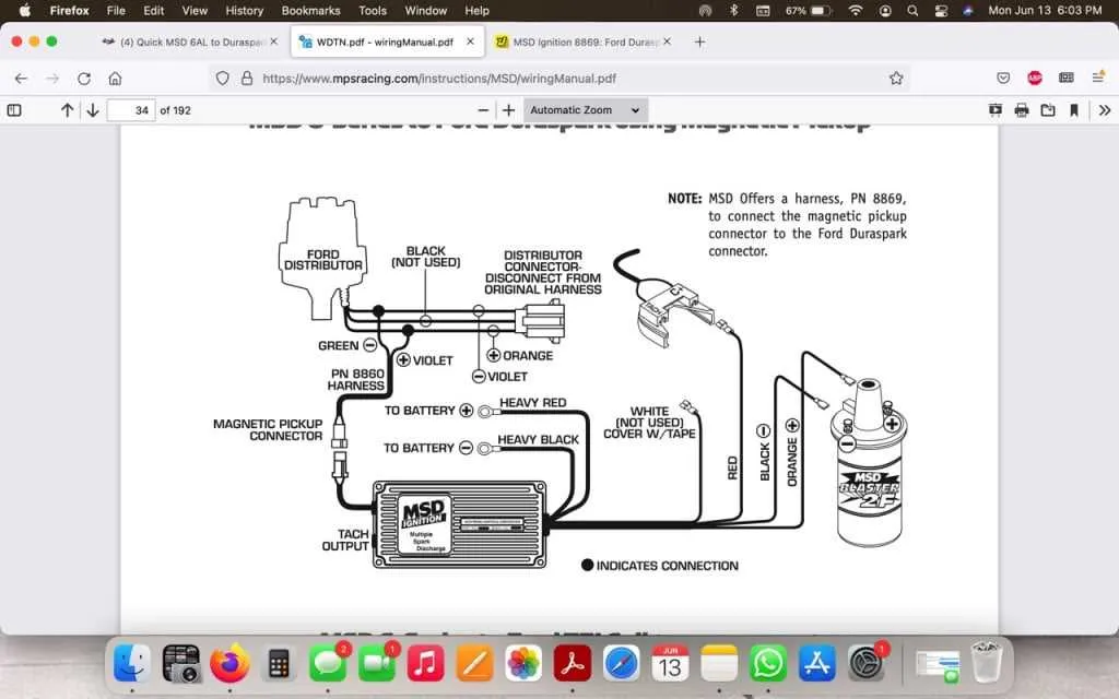
For optimal engine performance, ensure precise connections when setting up your ignition control unit. Start by securing a reliable ground connection to avoid electrical interference. Use a high-quality wire for the signal input from your distributor to maintain accurate timing and avoid voltage drops. It’s critical to keep the wires as short as possible, particularly the one linking to the coil, to prevent signal degradation.
Important: Always double-check the voltage ratings before attaching the power wires to your ignition unit. An incorrect voltage could damage internal components and lead to erratic engine behavior. The ignition control unit should be mounted in a dry, secure location to prevent exposure to excessive heat and moisture.
Tip: If you’re unsure about wiring the tachometer, consider using a dedicated output from the unit, as this will reduce the risk of interference and ensure accurate RPM readings. Also, when connecting any external sensors or accessories, verify compatibility with your ignition system to prevent mismatches.
Understanding the Ignition System Connection
Ensure the power supply is connected correctly to the unit’s main terminal, which requires a 12V DC source. Use a reliable, high-current wire for this connection to avoid voltage drops during operation.
The ignition coil should be wired to the dedicated output terminal of the control box. Make sure to secure the connection using high-quality, insulated connectors to prevent accidental shorts.
For the tachometer, connect it to the designated tach output terminal. This allows precise monitoring of engine speed. Ensure the tach wire is of sufficient gauge to prevent signal interference.
Ground the system to a clean, metal surface to avoid electrical noise and ensure proper operation. The ground wire must be securely fastened and as short as possible to maintain signal integrity.
If a rev limiter is in use, connect it to the input terminal and verify that the setting corresponds to the desired RPM limit. Use a multimeter to check that the limiter is properly engaged before use.
Double-check all connections before powering on the system. Loose or poor-quality connections can lead to misfires, erratic performance, or even system failure. Always use a professional-grade tool for final tightening and securing of all terminals.
How to Connect the MSD Ignition Box to Your System

To integrate the MSD ignition control unit with your system, follow these precise steps:
1. Connect the red wire to a 12V ignition-switched power source. Ensure this wire is linked to a fused source to avoid electrical overload.
2. The black wire should be routed to a solid ground. A good chassis ground is essential to ensure proper operation and avoid signal interference.
3. Attach the white wire to the signal terminal of your distributor. This allows the ignition control box to receive the signal from the distributor’s rotor position.
4. Connect the green and violet wires to the coil’s negative and positive terminals, respectively. These will deliver the ignition signal and energy to the spark plugs.
5. For optimal timing, link the orange wire to the tachometer input. This will allow your tachometer to read engine RPM accurately.
6. If you are utilizing a rev limiter feature, connect the purple wire to the appropriate terminal of the rev limit control, if applicable.
Ensure all connections are secure, insulated, and free from any interference to guarantee reliable performance and longevity of the ignition system.
Step-by-Step Guide for Connecting the Ignition Module to the Coil and Distributor

Follow these instructions to properly set up the ignition controller with your coil and distributor:
- Prepare the Components: Ensure that the ignition module, coil, and distributor are accessible and that you have the necessary connectors and tools.
- Power Supply Connections:
- Connect the positive terminal of the ignition module to a 12V switched power source. Use a fuse to prevent damage to the system in case of a short circuit.
- The ground wire of the ignition unit should be securely connected to the vehicle’s chassis or battery ground to avoid electrical interference.
- Coil Integration:
- Connect the high-voltage wire from the coil to the designated output terminal on the ignition controller.
- Attach the low-voltage wire from the controller to the coil’s negative terminal. This will enable the controller to trigger the spark.
- Distributor Hookup:
- Run the appropriate signal wire from the ignition unit to the distributor’s pickup terminal.
- If necessary, install a resistor or other necessary component as specified in your unit’s manual to ensure proper signal processing.
- Timing Adjustments: After connections are secure, adjust the timing according to your engine’s requirements using the module’s controls. Follow the manufacturer’s guidelines for setting optimal advance settings.
- Final Checks:
- Double-check all connections for tightness and correctness.
- Verify that all grounds are solid and that no wires are exposed to avoid short-circuiting.
- Testing: Power up the system and observe the module’s operation. Ensure the engine starts and runs smoothly. If there are issues, troubleshoot the wiring connections and adjust timing if necessary.
Troubleshooting Common Wiring Issues with the MSD Digital 6AL

Ensure the ignition box is properly grounded to the vehicle’s chassis. A poor ground connection can cause erratic behavior or complete failure of the system. Make sure the ground wire is securely fastened to a clean, metal surface, free of paint or corrosion.
Check the power supply connections for proper voltage. A drop below 12V can result in inconsistent performance. Use a multimeter to verify the input voltage at the ignition box and at the power feed wire from the battery. A stable, consistent voltage is crucial for optimal performance.
If there’s no spark, inspect the connection from the ignition coil to the box. Loose or corroded connectors can disrupt the signal and prevent spark generation. Tighten any loose connectors and clean any corrosion on the terminals.
Examine the trigger wire from the distributor for any damage. A frayed or shorted trigger wire can prevent the system from receiving the signal it needs to fire the spark plugs. If necessary, replace the wire or re-route it to avoid any interference.
If misfires or engine stuttering occur, inspect the signal and power leads to the coil. A damaged or improperly shielded wire may introduce noise or cause an erratic spark. Use high-quality, shielded wire to prevent electrical interference.
Confirm the tachometer signal wire is properly connected. An incorrect or loose tach wire can result in inaccurate RPM readings, affecting timing and performance. Ensure the tach wire is connected to the correct terminal on the ignition box and that it is firmly secured.
Lastly, check for any shorts in the system. Any exposed or damaged wiring could cause a short, leading to system failure. Look for bare spots in the wire insulation and replace any faulty sections immediately.