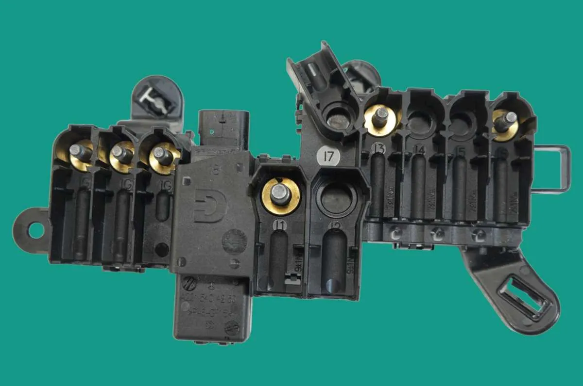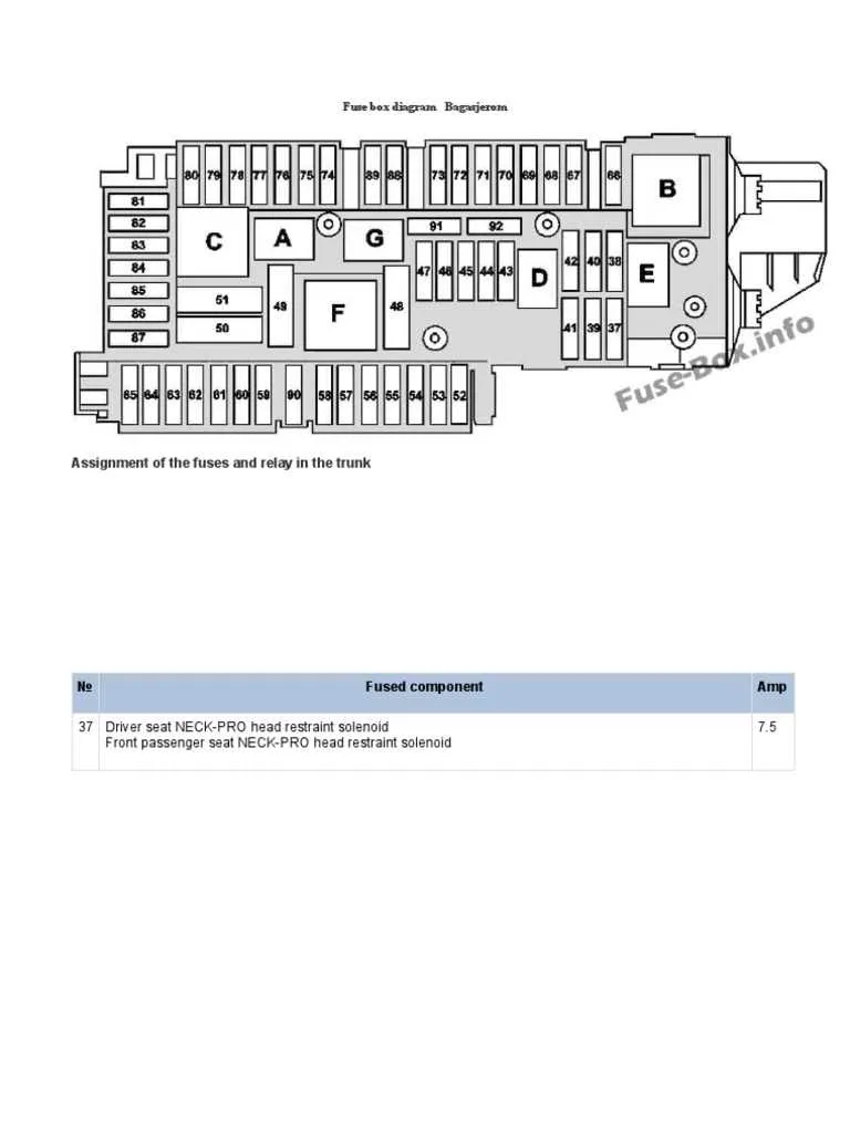
To efficiently troubleshoot or replace components within the main electrical control unit of this high-end vehicle, refer directly to the detailed schematic tailored for its internal power distribution. Identifying each protective element’s position and rating will ensure accurate handling of electrical faults and prevent unintended damage.
Access points are typically located beneath the dashboard on the driver’s side or inside the engine compartment near the battery. Familiarity with the precise arrangement of the circuit protectors can significantly reduce repair time and improve maintenance safety.
For optimal performance and safety, always cross-reference the assigned numbers and symbols marked on the cover with the corresponding elements in the vehicle’s maintenance manual. This practice aids in correctly diagnosing malfunctions related to lighting, climate control, and other critical subsystems.
Proper knowledge of this control layout not only helps in swift replacement but also safeguards the overall electrical system integrity during any modifications or upgrades.
Electrical Panel Layout for the Luxury Sedan
Locate the primary power distribution unit beneath the dashboard on the driver’s side for easy access. This panel organizes all critical protective elements safeguarding various circuits, including lighting, climate control, and infotainment systems.
The secondary assembly can be found within the engine compartment near the battery, responsible for handling higher current loads and essential engine management components. Each protective element is clearly labeled with its amperage rating, ensuring correct replacements.
For troubleshooting, refer to the owner’s manual section dedicated to electrical components. Identifying the exact slot related to malfunctioning systems is crucial for safe maintenance. Always disconnect the main power source before replacing any protective elements to avoid damage or injury.
Utilize specialized tools such as a test light or multimeter to verify continuity and proper function of these circuit protectors. Keeping a spare set of commonly used amperage units on hand is advisable for quick swaps during unexpected failures.
Locating the Main Electrical Panel in the Vehicle

The primary electrical distribution unit is positioned on the driver’s side, beneath the dashboard area, close to the left footwell. To access it, remove the lower panel trim located just above the pedals. The panel is secured with clips and may require gentle prying with a trim tool to avoid damage.
Additionally, a secondary power hub is housed within the engine compartment, near the battery terminal. This compartment contains high-amperage protective elements critical for the vehicle’s core functions. Inspect the plastic cover labeled with electrical symbols and unlatch it by releasing the securing tabs.
For quick identification, the internal layout of the protection elements is usually stamped on the underside of the panel lid, detailing amperage ratings and component assignments. This aids in pinpointing the exact location of individual protective units without removing them unnecessarily.
Ensure the ignition is switched off and the key is removed before attempting any inspection or replacement to prevent electrical shorts or injury. Use a flashlight for better visibility in tight spaces under the dashboard or engine bay.
Identifying and Understanding Fuse Functions by Position

Locate the panel cover and reference the internal layout chart to accurately pinpoint each protective element’s placement. Each slot corresponds to a specific electrical circuit critical for vehicle operation and comfort systems.
- Slot 1: Powers the ignition system, enabling engine start and run functions.
- Slot 3: Controls the power supply to the central locking and alarm units.
- Slot 7: Dedicated to the lighting control, including headlights and dashboard illumination.
- Slot 10: Protects the power outlets and accessory sockets.
- Slot 14: Manages the operation of the climate control module and ventilation fans.
- Slot 20: Supplies energy to audio and infotainment components.
To troubleshoot electrical failures, cross-check the specific location with the corresponding circuitry function. A burnt element in any slot usually indicates issues in that system, guiding targeted repairs or replacements.
- Consult the internal reference to match slot number and system role precisely.
- Use a multimeter or test light to verify continuity through the element in question.
- Replace only with components rated for the exact amperage specified for that position.
- Re-examine the system after replacement to ensure full restoration of functionality.
Keep a clear map or legend near the power distribution panel for quick identification and maintenance, preventing confusion during emergency fixes or routine checks.
Step-by-Step Guide to Replacing Fuses Safely
Begin by disconnecting the vehicle’s battery to prevent electrical shock or damage. Locate the protective casing housing the circuit protectors, then carefully open it using the appropriate tool, usually a small screwdriver or latch release.
Identify the faulty component by checking for a visible break or discoloration in the wire element inside each protective device. Use a tester or continuity meter for precise verification if necessary.
Remove the defective unit with a pair of insulated tweezers or a fuse puller to avoid direct contact with terminals. Ensure the replacement component matches the exact amperage rating printed on the original to maintain system integrity.
Insert the new protective element firmly into the designated slot, making sure it fits snugly without forcing it. Close the protective enclosure securely, confirming that all clips or screws are fastened to avoid vibration-related issues.
Reconnect the power source and test the associated electrical function to verify the repair. If the circuit breaks again immediately, further diagnosis is needed to identify underlying causes such as shorts or overloaded wiring.