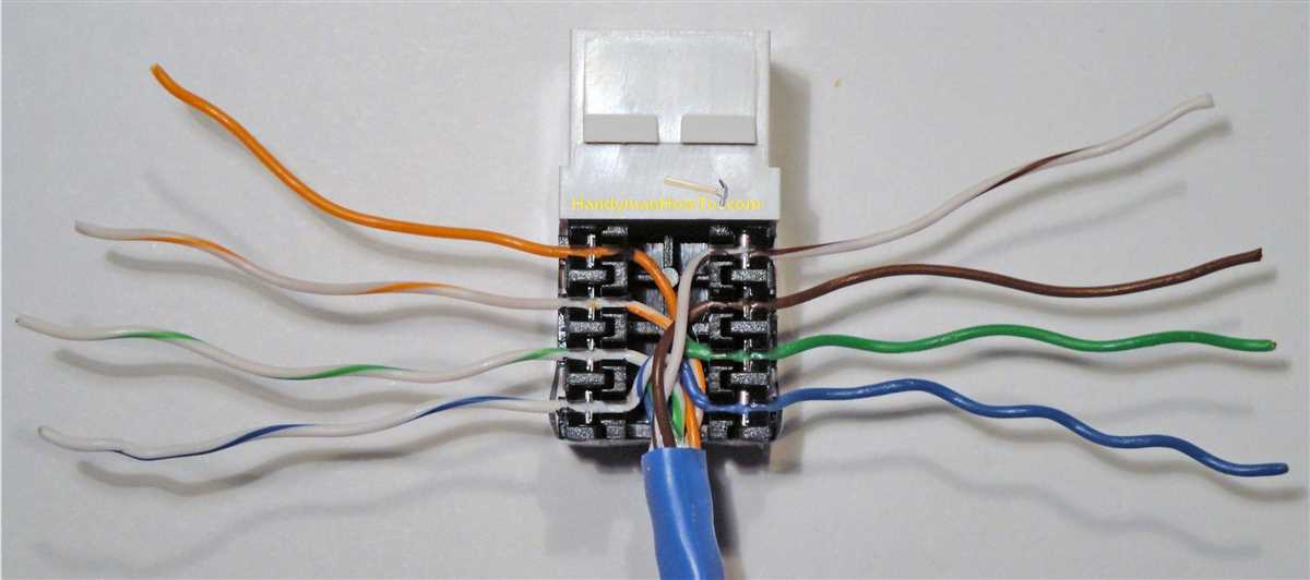
Phone wire connection diagram is a useful tool that helps in understanding and troubleshooting the wiring connections in a phone line. Whether you are installing a new phone line or trying to troubleshoot an existing one, having a clear and accurate diagram can save you time and effort.
The diagram typically shows the different wires and their colors that are used in a phone line. It also illustrates how these wires are connected to various components like the phone jack, telephone outlet, and the telephone exchange. Understanding these connections is important for ensuring that the phone line works properly and that the signal is transmitted efficiently.
Phone wire connection diagrams are especially helpful for DIY enthusiasts who want to install their own phone lines. By following the diagram, they can easily connect the wires correctly and avoid any mistakes that could lead to a faulty connection. Additionally, the diagram can also be used by professionals who are troubleshooting issues with the phone line, as it provides a visual representation of the connections.
Overall, having a phone wire connection diagram is an essential reference tool for anyone dealing with phone line installations or troubleshooting. It provides a clear and accurate guide to ensure that the wiring connections are set up correctly and that the phone line functions properly. Whether you are a DIY enthusiast or a professional, referring to the diagram can save you time, effort, and unnecessary frustration.
Understanding Phone Wire Connection Diagrams
Phone wire connection diagrams are valuable tools for understanding the layout and configuration of telephone wiring systems. These diagrams provide a visual representation of how telephone wires are connected to various components, such as telephone jacks, terminals, and distribution panels. They play a crucial role in troubleshooting phone line issues, expanding phone systems, or installing new telephone connections.
Phone wire connection diagrams typically depict different colors of wires, each representing a different function or purpose. For example, red and green wires are commonly used for connections between telephones and telephone jacks, while yellow wires may be used for intercom connections. By following these diagrams, technicians can ensure that the correct connections are made, preventing any possible cross-talk or signal interference.
One important aspect of understanding phone wire connection diagrams is familiarizing oneself with the various symbols used. These symbols can represent different types of wires, connections, or terminals, and understanding their meanings is crucial to accurately interpreting the diagram. Some common symbols include a squiggly line for a physical wire connection, a circle with a cross for a telephone jack or terminal, and a rectangle for a distribution panel or PBX system.
Phone wire connection diagrams are commonly provided by telephone service providers, equipment manufacturers, or can be found in relevant technical documentation. These diagrams are usually accompanied by explanatory text or a key that explains the different symbols and colors used. By referring to these diagrams, technicians can easily identify specific wires or components, pinpoint any potential issues, and ensure proper connectivity within a telephone system.
In conclusion, understanding phone wire connection diagrams is crucial for anyone involved in the installation, maintenance, or troubleshooting of telephone systems. These diagrams provide an organized and systematic representation of telephone wiring, allowing technicians to easily follow the correct connections and ensure optimal performance of the system.
What is a Phone Wire Connection Diagram?
A phone wire connection diagram is a visual representation of the wiring connections used to connect a telephone system. It shows how different wires and cables are connected to specific components in the system, such as telephone jacks, extension lines, and main distribution frames.
The diagram typically includes detailed information about the color codes and positions of individual wires within a telephone cable. This helps technicians and installers understand the correct wiring configurations and ensure proper connections are made.
Key elements:
- Telephone jacks: The diagram shows the different types of jacks used in the telephone system, such as wall jacks or modular jacks, and how they are connected to the wiring.
- Extension lines: It illustrates the wiring connections for extension lines, which allow multiple phones to be connected to the same telephone line.
- Main distribution frames: This component connects the telephone lines from the service provider to the internal telephone system. The diagram shows how the main distribution frame is connected to the rest of the system.
- Color codes: The diagram provides information about the color codes used for the different wires, such as red for line 1 and green for line 2. This helps ensure consistency and clarity when making connections.
Overall, a phone wire connection diagram is an essential tool for anyone involved in installing, troubleshooting, or maintaining telephone systems. It provides a clear and organized reference for understanding the complex network of wiring connections in a phone system.
Types of Phone Wire Connection Diagrams
Phone wire connection diagrams are essential for understanding how to properly connect phone wires in various situations. There are several types of phone wire connection diagrams, each designed for specific purposes and configurations.
1. Standard Phone Wire Connection Diagram
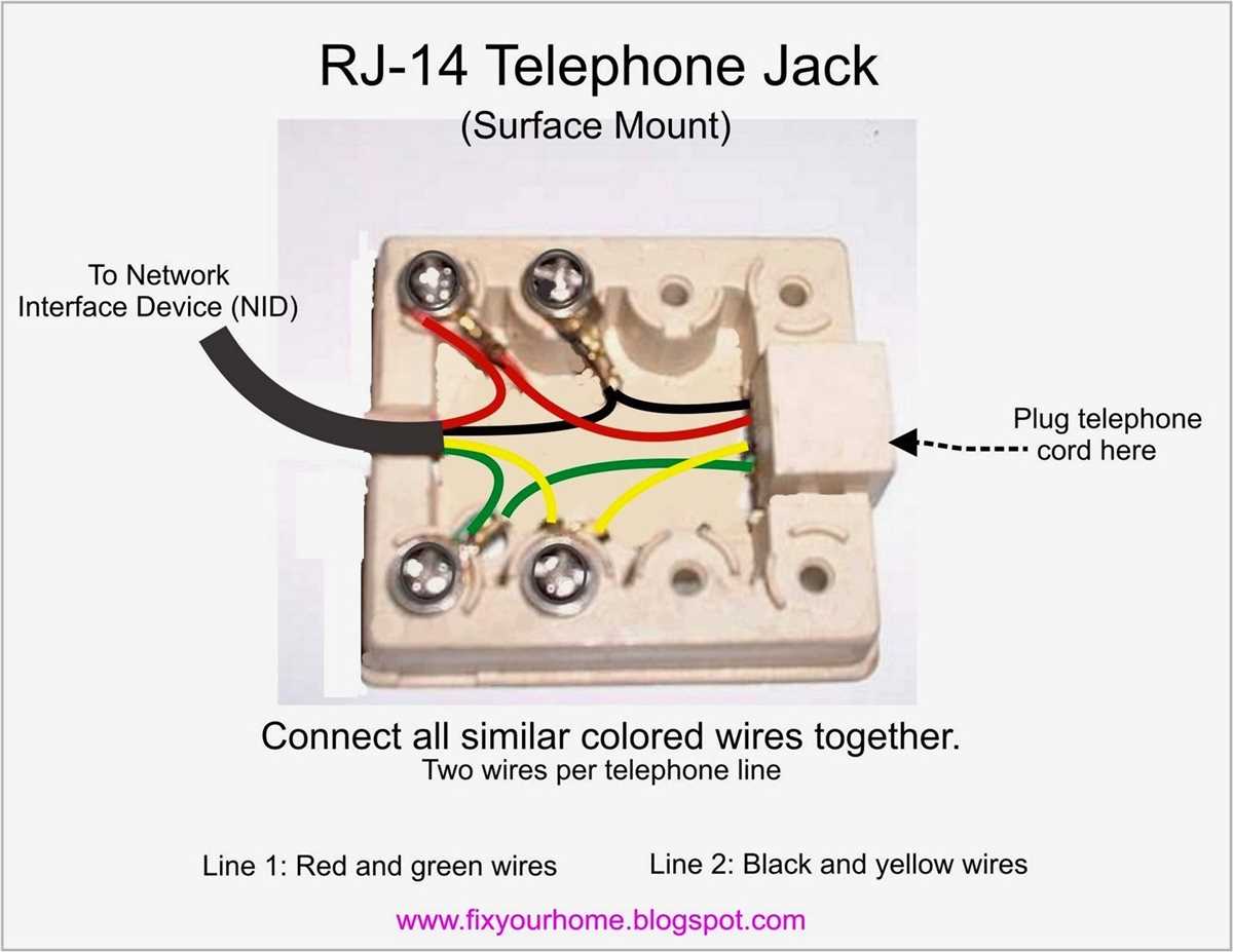
The standard phone wire connection diagram is the most common and basic diagram used to connect phone lines. It typically consists of two pairs of wires: a pair for the line and a pair for the voltage supply. The diagram shows how these wires should be connected to the phone jack and the telephone device.
Example:
- Line Wire Pair: Red and Green
- Voltage Supply Wire Pair: Black and Yellow
2. DSL Phone Wire Connection Diagram
A DSL (Digital Subscriber Line) phone wire connection diagram is specifically designed for connecting phone lines in DSL setups. DSL technology allows for high-speed internet access over traditional phone lines. The diagram outlines the connections between the DSL modem, phone jack, and telephone device.
Example:
- DSL Line Wire Pair: Blue and White
- Voltage Supply Wire Pair: Black and Yellow (similar to standard diagram)
3. VoIP Phone Wire Connection Diagram
A VoIP (Voice over Internet Protocol) phone wire connection diagram is used to connect phone lines in VoIP setups. VoIP technology enables voice communication over the internet instead of traditional phone lines. The diagram shows how to connect the VoIP adapter, router, phone jack, and VoIP phone.
Example:
- VoIP Line Wire Pair: Orange and White
- Voltage Supply Wire Pair: Black and Yellow (similar to standard diagram)
These are just a few examples of phone wire connection diagrams. Depending on the specific configuration and purpose, there can be other types of diagrams as well. It is important to consult the appropriate diagram and follow the instructions carefully to ensure proper phone line connections.
Basic Components of a Phone Wire Connection Diagram
A phone wire connection diagram is a visual representation of the various components and connections involved in setting up a telephone line. It provides a clear and organized way to understand and troubleshoot the wiring system. There are several basic components that are typically included in a phone wire connection diagram.
1. Telephone Line:
The telephone line is the main connection between the telephone company’s network and the telephone equipment in a building. It carries the electrical signals that transmit voice and data communication. In a phone wire connection diagram, the telephone line is usually represented by a solid line with two or more wires within it.
2. Telephone Jacks:
Telephone jacks, also known as modular connectors or RJ-11 jacks, are used to connect telephones or other devices to the telephone line. They provide a standardized connection point for the phone wire to be plugged in. In a phone wire connection diagram, telephone jacks are often represented by small rectangles or squares with a dashed or solid line connecting them to the telephone line.
3. Phone Cables:
Phone cables, also called twisted pair cables, are used to carry the electrical signals between the telephone line, telephone jacks, and other telephone equipment. They consist of multiple pairs of insulated wires twisted together to reduce electromagnetic interference. In a phone wire connection diagram, phone cables are typically represented by lines with multiple parallel dashes or dots.
4. Splitter:
A splitter is a device used to divide the phone signal into separate voice and data signals. It is often used in situations where both telephone and internet services are provided over the same phone line. In a phone wire connection diagram, a splitter is represented by a rectangular box with multiple incoming and outgoing lines.
5. Patch Panel:
A patch panel is a centralized distribution point for connecting various telephone lines and devices. It allows for easy management and organization of the phone wiring system. In a phone wire connection diagram, a patch panel is often depicted as a rectangular box with multiple rows of connectors.
These are just a few of the basic components that can be found in a phone wire connection diagram. Understanding the layout and connections of these components is essential for proper installation, maintenance, and troubleshooting of telephone systems.
How to Read a Phone Wire Connection Diagram
When it comes to setting up or troubleshooting phone wire connections, having a clear understanding of a phone wire connection diagram can be extremely helpful. A phone wire connection diagram is a visual representation of the different components and connections involved in a telephone system. By understanding how to interpret this diagram, you can easily identify the different wires, connectors, and terminals involved in the phone wiring.
1. Determine the type of connection diagram: There are different types of phone wire connection diagrams, depending on the specific phone system and wiring configuration. Some common types include the standard 4-wire configuration, the 6-wire configuration, and the modular connector configuration. Identify which type of diagram you are working with in order to properly interpret it.
2. Identify the components: Look for the key components represented in the diagram, such as the telephone line interface unit, junction box, and various phone jacks. These components are typically labeled and shown with corresponding symbols to make them easily recognizable.
3. Follow the wiring connections: Each wire in the diagram is labeled with a specific color code and may have a corresponding number or letter. Follow the path of each wire to understand how they are connected to each component. Pay attention to any special markings or symbols that indicate specific connections, such as a dashed line for a shared line or a double line for a twisted pair.
4. Understand the function of each wire: Different wires in the phone wire connection diagram serve different purposes. For example, the red and green wires are typically used for the primary phone line, while the yellow and black wires are used for a secondary line. By understanding the function of each wire, you can troubleshoot issues more effectively.
5. Refer to the legend or key: Most phone wire connection diagrams will include a legend or key that explains the different symbols and color codes used. Make sure to refer to this key if you come across any unfamiliar symbols or codes.
By following these steps and familiarizing yourself with the different components and connections in a phone wire connection diagram, you can confidently set up and troubleshoot phone wiring in your home or office.
Common Issues with Phone Wire Connection Diagrams
Phone wire connection diagrams are essential for properly connecting phone lines and ensuring clear communication. However, there are some common issues that can arise when using these diagrams. Understanding these issues can help troubleshoot problems and ensure a successful connection.
1. Incorrect Wiring
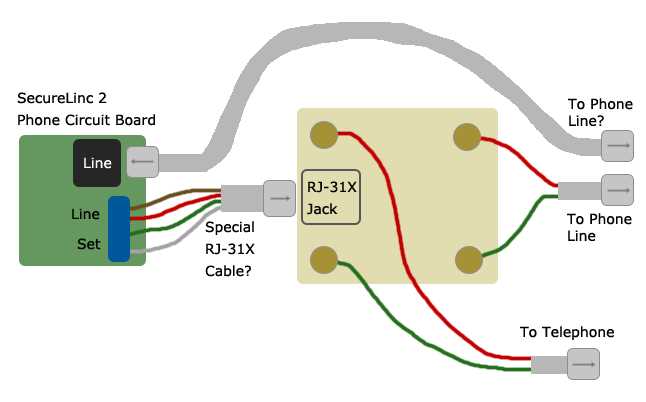
One of the most common issues with phone wire connection diagrams is incorrect wiring. This can occur when the diagram is not followed accurately or when there are errors in the diagram itself. Incorrect wiring can lead to distorted audio, no dial tone, or a complete lack of connectivity. To avoid this issue, it is important to double-check the diagram and ensure that the wires are connected to the correct terminals.
2. Malfunctioning Equipment
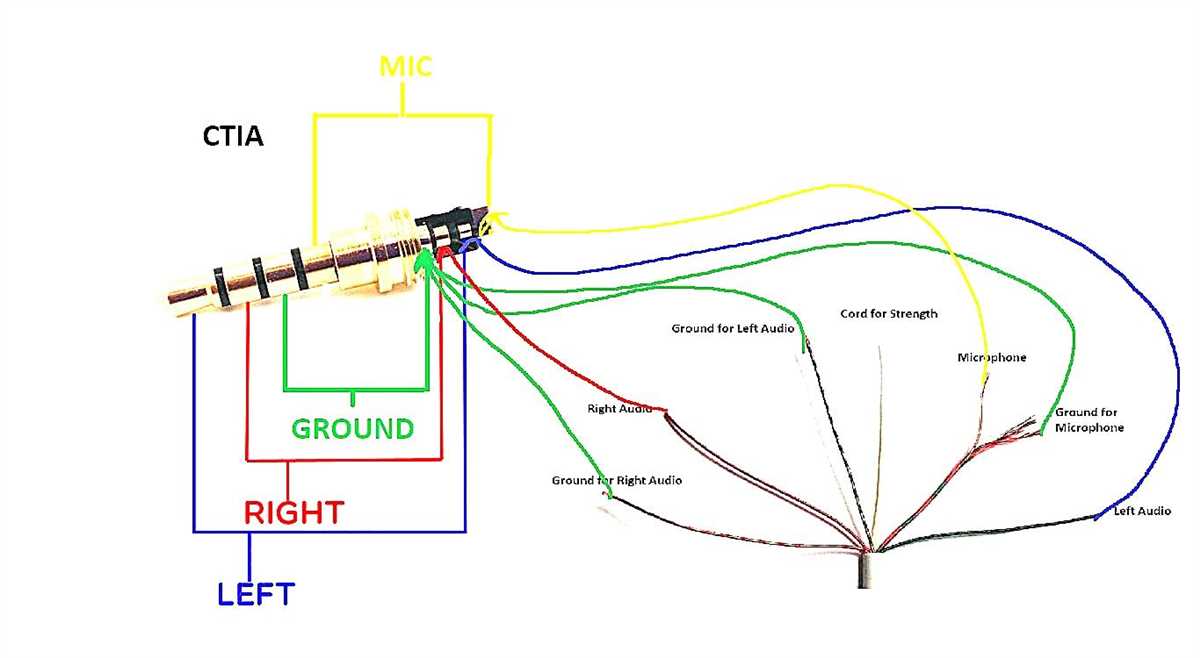
Another potential issue with phone wire connection diagrams is malfunctioning equipment. Even if the wiring is correct, faulty hardware can still cause problems. This can include damaged phone jacks, defective wiring connectors, or malfunctioning phones. It is important to inspect all the equipment involved in the phone connection and replace any faulty components.
3. Incompatible Wiring Standards
Phone wire connection diagrams may vary based on the wiring standards used in different regions or by different telecommunications providers. In some cases, incompatible wiring standards can cause issues when attempting to connect phone wires. It is important to ensure that the diagram being used aligns with the specific wiring standards in place. Consulting with a professional or referring to the documentation provided by the telecommunications provider can help resolve any compatibility issues.
4. Poor Cable Quality
Poor cable quality can also contribute to problems with phone wire connections. Low-quality cables or those that have been damaged or improperly installed can result in interference, reduced signal quality, or even complete signal loss. Using high-quality, properly installed cables can help alleviate these issues and ensure a reliable phone connection.
5. Lack of Proper Grounding
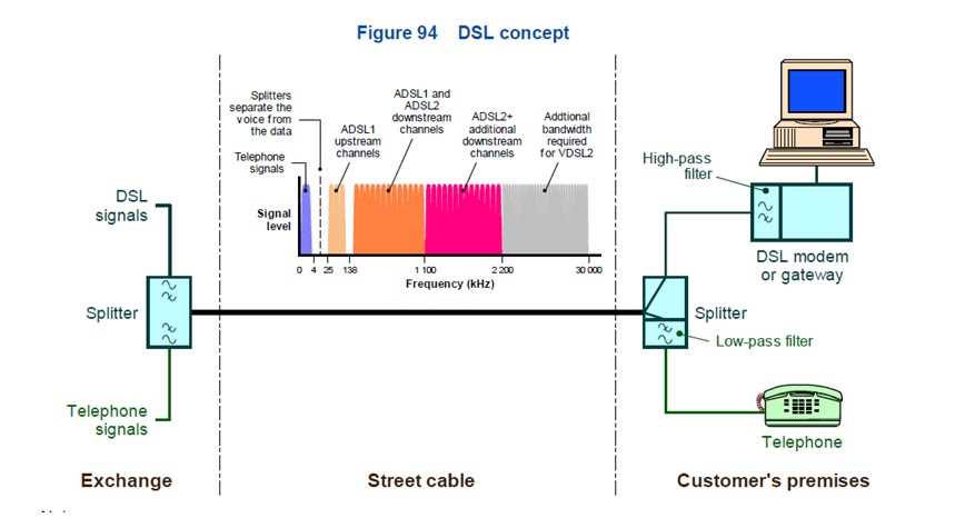
An often overlooked issue with phone wire connections is the lack of proper grounding. Proper grounding ensures that any excess electrical current is safely discharged and prevents interference or damage to the phone lines. If the phone wire connection diagram does not include instructions for grounding, it is important to consult with a professional or refer to the appropriate documentation.
Overall, being aware of these common issues and taking steps to address them can help ensure a successful phone wire connection. Checking for correct wiring, inspecting equipment, verifying compatibility with wiring standards, using high-quality cables, and ensuring proper grounding are all important factors in achieving clear and reliable phone communication.
Tips for Creating a Phone Wire Connection Diagram
Creating a phone wire connection diagram can seem overwhelming, but with the right tips and guidelines, it can be a straightforward process. Here are some tips to help you create an accurate and practical phone wire connection diagram:
- Understand the phone wire and its components: Before creating a diagram, it’s essential to have a clear understanding of the phone wire and its different components. This includes familiarizing yourself with the wires, connectors, jacks, and any other relevant elements.
- Label the wires: When creating the diagram, make sure to label each wire correctly. This will help ensure that the connections are accurate and easy to follow. Use clear and descriptive labels to avoid confusion.
- Use colors and symbols: Incorporating colors and symbols into your diagram can make it easier to understand and follow. Different colors can represent specific wires or connections, while symbols can indicate different types of components or actions.
- Keep it organized: To avoid confusion, it’s crucial to keep your phone wire connection diagram organized. Use a logical layout that flows from left to right or top to bottom. Use dashed lines or arrows to indicate the direction of the wire connections.
- Include a legend: In complex diagrams, consider including a legend that explains the meaning of different symbols and colors used. This will make it easier for others to understand and interpret the diagram correctly.
- Double-check your work: Before finalizing your connection diagram, double-check all the connections and labels to ensure they are accurate. Mistakes in the diagram can lead to errors in the actual phone wiring, so it’s important to be thorough.
By following these tips, you can create a phone wire connection diagram that is clear, accurate, and easy to understand. Whether you are setting up a new phone system or troubleshooting an existing one, a well-designed diagram can be a valuable tool. Remember to keep it organized, label everything correctly, and double-check your work for the best results.