
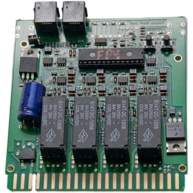
When it comes to building a model railroad layout, one of the key challenges is establishing a reliable and efficient power distribution system. Digitrax, a leading manufacturer of model railroad control systems, offers a solution with the PM42 Wiring Panel. This compact and easy-to-install device allows model railroaders to distribute power to multiple track sections, effectively reducing the risk of short circuits and ensuring smooth operation of locomotives.
The PM42 Wiring Panel consists of four separate power districts, each capable of handling up to 5 amps of power. By dividing the layout into smaller sections, model railroaders can isolate any problems that occur, preventing them from affecting the entire system. This innovative wiring panel also features built-in short circuit protection, automatically shutting down power to the affected district while allowing the rest of the layout to continue operating.
With its user-friendly design and versatile capabilities, the PM42 Wiring Panel is suitable for layouts of all sizes and complexity levels. Whether you’re a beginner or an experienced model railroader, this device streamlines the wiring process, making it easier to create a more reliable power distribution system. By using the PM42 Wiring Panel, you can spend less time troubleshooting electrical issues and more time enjoying the hobby.
Digitrax PM42 Wiring Guide
The Digitrax PM42 is a power manager that allows you to divide and distribute power to different sections of your model railroad layout. It is an essential component for ensuring smooth and efficient operation of your trains. In this wiring guide, we will discuss the proper installation and wiring of the PM42.
Step 1: Mounting the PM42
Before starting the wiring process, make sure to mount the PM42 in a suitable location on your layout. It is recommended to mount it vertically on a wall or layout fascia for easy access. You can use screws or double-sided adhesive tape to secure it in place.
Step 2: Connecting the Power Supply
To provide power to the PM42, you will need to connect a DC power supply. Use a wire stripper to remove a small section of insulation from the power supply wires. Insert the exposed wires into the power input terminals on the PM42 and tighten the screws to secure the connection. Make sure to connect the positive (+) wire to the B for Booster terminal and the negative (-) wire to the G for Ground terminal.
Step 3: Wiring the Power Outputs
The PM42 features four power output terminals labeled A, B, C, and D. These terminals are used to distribute power to different sections of your layout. To wire the power outputs, strip a small section of insulation from the wires for each section and connect them to the corresponding terminals on the PM42. Make sure to use wire connectors or solder the connections for a secure and reliable connection.
Step 4: Adding Circuit Breakers
To protect your layout from short circuits and excessive current draw, it is recommended to add circuit breakers to each power output section. The PM42 has built-in auto-resetting circuit breakers, but additional circuit breakers can be added for extra protection. Connect the circuit breakers between the PM42 power outputs and the track feeders to ensure that any short circuit or excessive current will be detected and isolated.
Step 5: Testing and Troubleshooting
After completing the wiring, it is important to test the PM42 and ensure that power is being properly distributed to the different sections of your layout. Use a multimeter to check the voltage at each power output terminal and make any necessary adjustments or corrections. If you encounter any issues, refer to the PM42 manual or seek assistance from the Digitrax support team.
By following this wiring guide, you will be able to properly install and wire the Digitrax PM42 power manager for your model railroad layout. This will help ensure smooth and efficient operation of your trains, while also providing protection against short circuits and excessive current draw.
Overview
The Digitrax PM42 is a circuit breaker and occupancy detector designed for model railroads. It is used to detect shorts or excessive electrical current draw in your layout and protect your trains and accessories from damage. The PM42 can be connected to multiple power districts, allowing you to easily monitor and control each section of your layout separately. This ensures that a short or overload in one area doesn’t affect the rest of your layout.
The PM42 features four outputs, each capable of handling up to 4 amps of current. Each output has a corresponding light-emitting diode (LED) that indicates the status of that power district. When the LED is off, the corresponding power district is not active. When the LED is on, the power district is active and functioning normally. If the LED starts blinking or turns off completely, this indicates a short or overload in that power district.
In addition to its circuit breaker function, the PM42 also acts as an occupancy detector. It can sense the presence of a train or other rolling stock in the monitored power districts and send this information to your command station or computer. This allows you to track the location of your trains and operate signals and other accessories based on their position.
To wire the PM42, you will need to connect your power supply, command station, and power districts to the appropriate terminals on the unit. The PM42 is designed to be easily integrated into your existing layout and can be used with a variety of Digital Command Control (DCC) systems. It is a versatile and essential component for any model railroad enthusiast looking to protect their trains and improve operational control.
Choosing the Right Power Supply for Your PM42
The PM42 is a crucial component of your Digitrax DCC system, as it provides protection and power distribution for your layout. However, to ensure optimal performance, it’s important to choose the right power supply for your PM42. Here are a few factors to consider:
1. Power Output
Your power supply should be capable of providing enough power to meet the demands of your layout. The PM42 can handle up to 5 amps, so make sure your power supply can deliver this amount of power or more to avoid any potential issues with underpowered operation.
2. Voltage Compatibility
Ensure that your power supply is compatible with the voltage requirements of your PM42. The PM42 requires a power supply that can deliver between 12-18 volts DC. Using a power supply with a voltage outside this range can result in damage to the PM42 or inconsistent operation.
3. Quality and Reliability
Investing in a high-quality power supply can greatly improve the overall performance and longevity of your PM42. Look for power supplies from reputable manufacturers known for their reliability and durability. Avoid inexpensive, low-quality power supplies that may not provide stable and consistent power output.
4. Safety Features
Ensure that your power supply has built-in safety features to protect your PM42 and other components from potential electrical issues. Features like short-circuit protection, over-current protection, and thermal protection can help prevent damage to your equipment in case of a power surge or other electrical problems.
5. Future Expansion
Consider your future expansion plans when choosing a power supply for your PM42. If you plan to expand your layout in the future, make sure your power supply has enough capacity to handle the increased power demands. Choosing a power supply with room for growth can save you from having to upgrade in the future.
By considering these factors when choosing a power supply for your PM42, you can ensure that your DCC system operates smoothly and reliably, allowing you to fully enjoy your model railroad hobby.
Wiring the PM42 to the Power Supply
The PM42 is a power management device that is used to protect and isolate sections of a model railroad layout. It is designed to prevent shorts and overloads from damaging the power supply or other components. When wiring the PM42 to the power supply, there are a few key steps to follow to ensure proper installation and operation.
Step 1: Connect the Power Supply
The first step is to connect the power supply to the PM42. This is typically done using the screw terminals on the device. The power supply should be connected to the screw terminals labeled “Power In” or something similar. It is important to ensure that the positive and negative terminals of the power supply are connected correctly to the PM42.
Step 2: Connect the Track Bus
Next, the track bus, which carries power to the track sections, should be connected to the PM42. This is typically done using the screw terminals labeled “Track Bus” or something similar. It is important to ensure that the track bus is connected to the correct terminals on the PM42 to ensure proper power distribution.
Step 3: Connect the Track Sections
Once the power supply and track bus are connected to the PM42, the individual track sections can be connected. This is typically done using the screw terminals labeled “Track Out” or something similar. Each track section should have its own screw terminal to prevent shorts and overloads from affecting other sections of the layout. It is important to ensure that the track sections are connected to the correct terminals on the PM42.
Overall, wiring the PM42 to the power supply involves connecting the power supply to the device, connecting the track bus to distribute power, and connecting the individual track sections. Following these steps will ensure proper installation and operation of the PM42 in a model railroad layout.
Connecting the PM42 to Your DCC System
The PM42 is a vital component in any DCC system as it serves as a power management device. It ensures a smooth running of your model railroad by protecting your layout and locomotives from short circuits and electrical overloads. Before connecting the PM42, it is important to understand its wiring requirements and how it integrates into your DCC system.
Power input: The PM42 requires a separate power source. It should be connected to a power supply that can provide sufficient voltage and current to meet the needs of your layout. The power supply should be able to handle the total amperage requirements of your entire DCC system, including the PM42 and all the connected locomotives and accessories.
Power output: The PM42 features four power districts, each capable of handling up to 8 amps of current. These power districts allow you to divide your layout into several sections, which can be independently controlled and protected. It is important to properly wire and isolate each power district to prevent short circuits and electrical interference.
Wiring: To connect the PM42 to your DCC system, start by connecting the power input terminals to the power source. Make sure to observe the correct polarity to avoid damaging the PM42. Next, wire the power output terminals of each power district to the corresponding track sections. It is recommended to use bus wires and terminal blocks for a neat and organized wiring. Finally, connect the PM42 to your command station or DCC booster using the provided cables or wires.
Programming: After connecting the PM42, you may need to program it to set the current thresholds and configure the auto-reversing feature, if applicable. Refer to the PM42 manual and the documentation of your DCC system for specific instructions on how to program and configure the PM42.
By properly connecting the PM42 to your DCC system, you can ensure the safe and efficient operation of your model railroad, protecting your layout and locomotives from electrical issues. Always follow the manufacturer’s guidelines and safety precautions when working with electrical components.
Testing and Troubleshooting the PM42
The Digitrax PM42 is a power manager that is commonly used in digital model railroad systems to provide protection for the layout and the digital command control (DCC) equipment. It helps prevent short circuits and overloads by dividing the layout into multiple power districts. However, like any electronic device, the PM42 can sometimes experience issues and require testing and troubleshooting to identify and resolve the problem.
1. Visual Inspection:
Before testing, it is important to conduct a visual inspection of the PM42 and its wiring. Check for any loose or disconnected wires, damaged insulation, or signs of overheating. Ensure that all connections are secure and that the PM42 is properly grounded. Fix any visible issues before proceeding with further testing.
2. Power Verification:
To verify if the PM42 is receiving power, use a multimeter to measure the voltage at the input terminals. The PM42 should receive the appropriate voltage according to the manufacturer’s specifications. If there is no power, check the power supply, fuse, and wiring connections. Replace any faulty components if necessary.
3. District Testing:
Disconnect all power to the layout and connect the PM42 to the DCC system. Turn on the power and test each power district individually. Use a multimeter to measure the voltage at the output terminals of each district. The voltage should match the expected DCC voltage. If there is no voltage, check the wiring connections between the PM42 and the track. Look for any loose or broken wires and repair as needed.
4. Short Circuit Detection:
The PM42 is equipped with short circuit protection to prevent damage to the layout and equipment. To test the short circuit detection, intentionally create a short circuit on one of the power districts. The PM42 should detect the short circuit and immediately shut off power to that district. If the short circuit protection does not work, check the PM42’s manual for troubleshooting steps or contact the manufacturer for support.
5. Advanced Troubleshooting:
If the PM42 still experiences issues after performing basic tests and troubleshooting, consult the manufacturer’s documentation or seek assistance from a knowledgeable technician. They may be able to provide more advanced troubleshooting steps or suggest a repair or replacement for the PM42.
By following these testing and troubleshooting steps, it is possible to identify and resolve issues with the Digitrax PM42 power manager. Regular maintenance and testing can help ensure the smooth operation of the DCC system and the protection of the model railroad layout.
Additional Resources for PM42 Wiring
Now that you have a basic understanding of PM42 wiring for your Digitrax system, there are additional resources available to help you further explore and troubleshoot any issues you may encounter. These resources will provide you with more in-depth information and guidance on PM42 wiring and its various applications.
Digitrax Manuals and Documentation
The best place to start is with the official Digitrax manuals and documentation. These resources provide detailed information on the installation, configuration, and troubleshooting of the PM42 and other Digitrax products. You can find these manuals on the Digitrax website or included with your PM42 purchase.
- Digitrax Website: The Digitrax website is a valuable resource for finding manuals, documentation, and other technical information. Visit www.digitrax.com to access these resources.
- PM42 Manual: The PM42 manual provides step-by-step instructions for wiring and configuring the PM42 and can help you troubleshoot common issues. Make sure to review this manual thoroughly before beginning your PM42 installation.
Online Forums and Communities
Online forums and communities are a great place to connect with other model railroaders who have experience with PM42 wiring and Digitrax systems. These resources can provide valuable insights, tips, and troubleshooting advice. Here are a few popular forums and communities to check out:
- Model Railroad Hobbyist: Model Railroad Hobbyist is an online community with a dedicated forum section for DCC and Digitrax discussions. Visit https://model-railroad-hobbyist.com/forum to join the conversation.
- TrainBoard: TrainBoard is another popular forum where you can find discussions on various model railroad topics, including DCC and Digitrax. Check out their DCC forum at https://www.trainboard.com/highball/index.php?forums/dcc-model-railroad-electronics.54/.
YouTube Tutorials
YouTube is a treasure trove of tutorials and videos that can provide visual demonstrations and step-by-step instructions for PM42 wiring and configuration. Many model railroaders and DCC enthusiasts share their expertise on YouTube. Here are a few channels to get you started:
- Model Railroader: Model Railroader’s YouTube channel offers various videos on DCC and Digitrax systems. Their videos provide clear explanations and visual demonstrations of wiring and installation techniques. Visit their channel at www.youtube.com/modelra… for more information.
- North Coast Engineering (NCE): While NCE is a different DCC brand, their YouTube channel features informative videos on DCC wiring and troubleshooting that can be applied to PM42 and Digitrax systems. Explore their videos at www.youtube.com/NCEHobby.
By utilizing these additional resources, you will be well-equipped to tackle your PM42 wiring project and troubleshoot any issues that may arise. Remember to refer to the Digitrax manuals and documentation as your primary source of information, and don’t hesitate to seek guidance from online forums and tutorial videos. Happy wiring!