
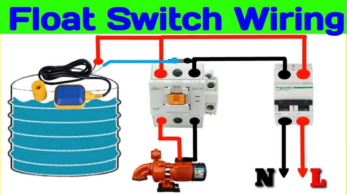
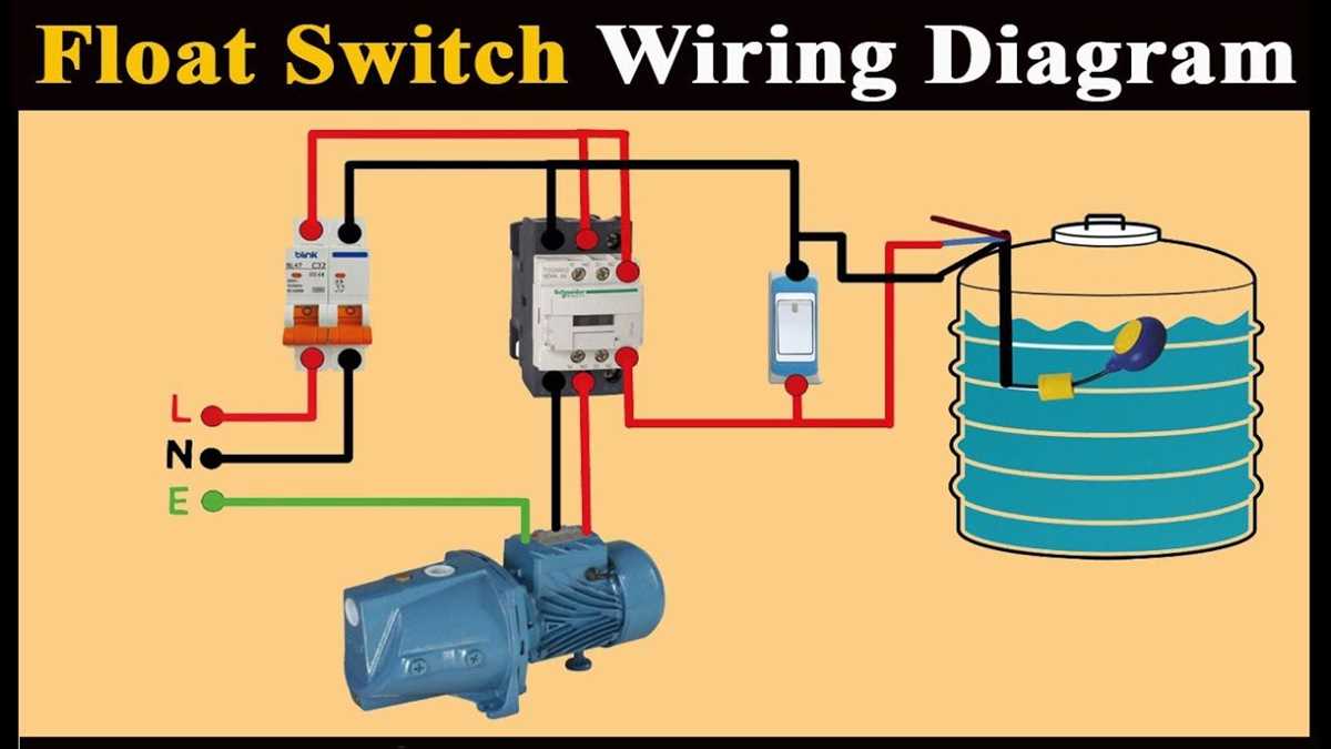
Attwood float switches are essential components used in marine applications to control the water level in bilge pumps and other water systems. These switches are designed to activate the pump when the water level rises above a certain threshold and deactivate it once the level drops below that threshold. Proper wiring is crucial to ensure the float switch functions correctly and reliably.
The Attwood float switch wiring diagram provides a visual representation of how the switch should be wired to the pump and power source. It shows the proper connections for the switch terminals, as well as the necessary fuses or circuit breakers that should be used for safety. Following the wiring diagram is essential to prevent electrical hazards and ensure the proper operation of the bilge pump system.
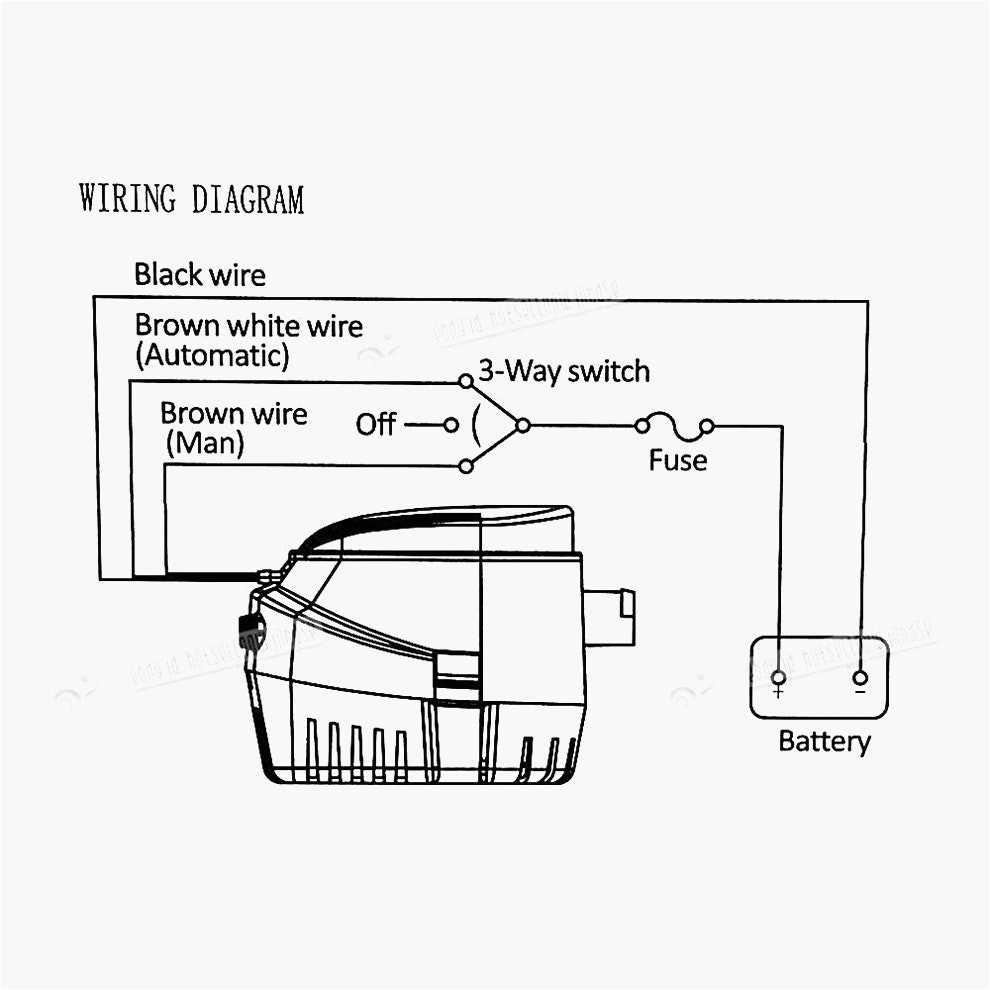
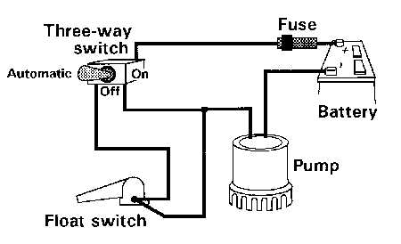
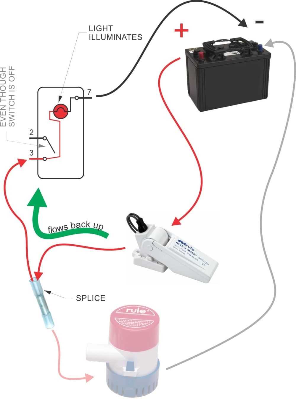
The most common Attwood float switch has three terminals: the positive terminal (+), the negative terminal (-), and the pump terminal. The positive and negative terminals are connected to the power source, while the pump terminal is connected to the pump itself. When the water level rises, the float switch tilts, completing a circuit between the positive and pump terminals, activating the pump. When the water level drops, the float switch returns to its original position, breaking the circuit and deactivating the pump.
Attwood Float Switch Wiring Diagram: A Detailed Guide

A float switch plays a crucial role in automatic pump control systems, ensuring that water levels are properly maintained. Attwood, a reputable manufacturer of marine and boating accessories, offers a line of float switches that are widely used in various applications.
When it comes to wiring an Attwood float switch, it is essential to follow a specific diagram to ensure correct installation and operation. Let’s take a closer look at a detailed guide on how to wire an Attwood float switch.
Step 1: Gather the Required Tools and Materials
Before getting started, make sure you have all the necessary tools and materials. This typically includes a wire stripper, crimping tool, electrical tape, wire connectors, and the Attwood float switch itself.
Step 2: Familiarize Yourself with the Attwood Float Switch
Take a moment to familiarize yourself with the Attwood float switch, understanding its different components, such as the float, switch housing, and wire leads. This will help you better understand the wiring diagram and ensure a successful installation.
Step 3: Review the Wiring Diagram
Attwood provides a wiring diagram specific to each model of float switch. Take the time to carefully review the diagram, noting the different wire colors and their corresponding connections. This will ensure that you wire the switch correctly and prevent any potential issues.
Step 4: Prepare the Wires
Using a wire stripper, carefully strip the ends of the wires according to the diagram’s specifications. Make sure to remove any outer insulation and expose enough bare wire to make a secure connection.
Step 5: Connect the Wires
Referencing the wiring diagram, begin making the appropriate connections. This may involve using wire connectors or crimping the wires together. Double-check each connection to ensure they are properly secured and insulated.
Step 6: Test the Float Switch
Once all the wires are connected, it is crucial to test the float switch before finalizing the installation. This can be done by manually moving the float up and down to simulate water level changes. Ensure that the switch operates correctly, activating and deactivating the pump as expected.
By following these steps and referencing the Attwood float switch wiring diagram, you can confidently wire your float switch and ensure reliable operation of your pump control system. Don’t forget to consult the manufacturer’s instructions and guidelines for any specific details related to your particular model of float switch.
Understanding the Basics of Attwood Float Switches
Attwood float switches are electrical devices used in marine applications to control the operation of bilge pumps. They are responsible for detecting the water level in the bilge area and automatically activating the pump to remove excess water. These switches are essential for ensuring the safety and functionality of boats, as they prevent the bilge area from flooding and potentially causing damage or sinking.
Attwood float switches operate on a simple principle: when water rises to a certain level, it lifts the switch’s float, which in turn triggers the switch to complete an electrical circuit. This circuit then activates the bilge pump, which begins pumping out the water. Once the water level decreases, the float falls back down, breaking the circuit and stopping the pump.
Attwood float switches are typically easy to install and require minimal wiring. The switches usually come with detailed wiring diagrams that guide users through the installation process. The wiring diagram for an Attwood float switch typically indicates which wires connect to the positive and negative terminals of the boat’s battery, as well as which wires connect to the bilge pump. Following the provided diagram is crucial to ensure that the switch is installed correctly and functions properly.
It is important to note that Attwood float switches come in different types, such as vertical and horizontal switches, which may have slightly different wiring configurations. Therefore, it is essential to consult the specific wiring diagram provided with the switch to ensure proper installation.
In conclusion, understanding the basics of Attwood float switches is crucial for boat owners and enthusiasts. These switches play a vital role in keeping the bilge area dry and preventing water damage to the boat. By following the provided wiring diagram and properly installing the switch, boat owners can ensure the reliable operation of their bilge pumps and the overall safety of their vessels.
Step-by-Step Float Switch Installation Guide

The Attwood float switch is a vital component for controlling the operation of your boat’s bilge pump. Installing a float switch ensures that your bilge pump automatically activates when water reaches a certain level, preventing flooding and damage to your vessel. Follow this step-by-step guide to correctly install the Attwood float switch for optimal performance and peace of mind.
1. Gather the necessary tools and materials:
- – Attwood float switch
- – Wire strippers
- – Electrical tape
- – Crimp connectors
- – Screws or zip ties for mounting the float switch
- – Screwdriver or drill (depending on mounting method)
- – Heat gun or lighter (optional)
2. Determine the mounting location:
Choose a location for the float switch that is convenient and easily accessible. Ideally, it should be placed in the lowest part of the bilge, ensuring accurate water level detection.
3. Mount the float switch:
- – Use screws or zip ties to securely attach the float switch to the chosen location. Make sure it is mounted in a way that allows the float to move freely with the water level.
- – If using screws, pre-drill pilot holes to avoid damaging the boat’s structure.
- – If using zip ties, ensure they are tightened enough to hold the float switch in place without restricting its movement.
4. Make electrical connections:
- – Strip approximately 0.5 inches of insulation from the wires connected to the float switch.
- – If using crimp connectors, insert the stripped wires into the connector and crimp them securely using a crimping tool.
- – If not using crimp connectors, twist the stripped wires together and use electrical tape to secure the connection. Optionally, use a heat gun or lighter to shrink the electrical tape for added protection.
- – Connect the float switch wires to the appropriate wires on the bilge pump or control panel. Refer to the manufacturer’s instructions or wiring diagram for guidance.
5. Test the float switch:
Once all connections are made, test the float switch by filling the bilge with water to the desired activation level. The float switch should activate the bilge pump and pump out the water. Ensure that the pump turns off once the water level drops below the float switch’s threshold.
6. Secure and tidy up:
Use zip ties or tape to secure any loose wires and prevent them from interfering with the float switch’s movement or becoming tangled. Ensure all connections are properly insulated using electrical tape or heat shrink tubing.
By following these steps, you can install and set up your Attwood float switch with confidence, providing reliable bilge pump activation and protection against water damage on your boat.
Wiring Diagram for Attwood Float Switch: Easy-to-Follow Instructions
The Attwood float switch is a key component in marine bilge pump systems, designed to automatically activate the pump when water reaches a certain level in the boat’s bilge compartment. Wiring the Attwood float switch correctly is crucial to ensure proper operation and prevent potential damage to the pump or boat.
Here is an easy-to-follow wiring diagram for the Attwood float switch:
Materials Needed:
- Attwood float switch
- Bilge pump
- Marine-grade wiring
- Fuse holder and fuse
- Solderless connectors
- Wire strippers
- Heat shrink tubing
- Electrical tape
Step-by-Step Wiring Instructions:
- Start by disconnecting the boat’s battery to ensure safety while working with electrical components.
- Locate the bilge pump and the Attwood float switch. The float switch should be positioned at the desired water level for pump activation.
- Strip approximately 1/4 inch of insulation from the ends of the wires connected to the float switch and pump.
- Using solderless connectors, join the positive (+) wire from the float switch to the positive (+) wire of the pump. Repeat this step for the negative (-) wires. Ensure a tight and secure connection.
- Slide heat shrink tubing over each solderless connector and use a heat source, such as a heat gun or a lighter, to shrink the tubing and provide additional insulation.
- Route the combined wires to the boat’s battery compartment, ensuring they are protected from potential damage or snagging.
- Install a fuse holder between the positive (+) wire and the boat’s battery. Refer to the manufacturer’s instructions for fuse rating recommendations.
- Connect the positive (+) wire from the fuse holder to the positive (+) terminal of the battery. Connect the negative (-) wire from the pump to the negative (-) terminal of the battery.
- Once all the connections are made, carefully inspect them to ensure they are secure and properly insulated.
- Reconnect the boat’s battery and test the bilge pump system by filling the bilge compartment with water. The pump should activate when the water reaches the desired level.
Following these step-by-step instructions and using the provided wiring diagram, you can easily wire the Attwood float switch to ensure reliable operation of your boat’s bilge pump system. Always prioritize safety and double-check all connections before returning power to the system.
Different Types of Attwood Float Switches and Their Wiring Diagrams
Attwood float switches are essential components in controlling the water level in various applications, such as bilge pumps, sump pumps, and water tanks. They come in different types, each designed for specific purposes. Here are some of the common types of Attwood float switches and their wiring diagrams:
1. Vertical Float Switch
The vertical float switch, also known as a hanging float switch, is one of the most common types. It consists of a cylindrical float that moves up and down with the water level. When the water level rises, the float buoyancy increases, causing the switch to turn on the pump. The wiring diagram for a vertical float switch usually includes three terminals: power, ground, and pump.
2. Horizontal Float Switch
The horizontal float switch is designed to be horizontally mounted within a tank or vessel. It uses a pivoting arm and a float to detect the water level. As the water level rises, the float moves the arm, triggering the switch to activate the pump. The wiring diagram for a horizontal float switch typically involves power, ground, and pump terminals, similar to the vertical float switch.
3. Electronic Float Switch
The electronic float switch incorporates advanced technology, replacing the traditional mechanical float. It utilizes sensors to detect the water level and sends signals to control the pump. These switches often offer additional features such as adjustable sensitivity and built-in alarms. The wiring diagram for an electronic float switch may vary depending on the specific model and brand.
4. Mercury Float Switch
The mercury float switch contains a sealed glass capsule with a drop of mercury inside. When the water level rises, the float lifts, tilting the capsule and allowing the mercury to bridge two contacts and complete the circuit. The wiring diagram for a mercury float switch generally includes power, ground, and pump terminals.
5. Wide Angle Float Switch
The wide-angle float switch, also known as a 90-degree float switch, offers a wider range of control over the water level. It uses an enclosed ball that rolls on a 90-degree arc, activating the switch at a set point. The wiring diagram for a wide-angle float switch typically involves power, ground, and pump terminals.
It is essential to refer to the specific manufacturer’s instructions and diagrams when installing Attwood float switches to ensure proper wiring and functionality. Incorrect wiring can lead to pump failure or other electrical issues, so always consult the appropriate documentation for your specific application.
Troubleshooting Common Problems with Attwood Float Switch Wiring
If you’re experiencing issues with your Attwood float switch wiring, don’t worry. Many common problems can be easily diagnosed and resolved with a little troubleshooting. Here are some common problems you may encounter and how to fix them:
Problem 1: Float switch not activating pump
If your float switch is not activating the pump, there are a few possible causes. First, check that the power source is functioning properly. Test the power outlet and ensure there is voltage present. If the power source is working, check the wiring connections at the float switch and the pump. Make sure the wires are securely connected and that there are no loose or damaged connections. Additionally, check the float switch itself. Ensure that it is not obstructed or stuck in the “off” position. If the float switch is clean and free from obstructions, it may need to be replaced.
Problem 2: Pump running continuously
If your pump is running continuously even when the float switch is in the “off” position, there may be a problem with the wiring. Check the wiring connections at the float switch and the pump to ensure they are correct and secure. If the connections are good, the issue may be with the float switch itself. Inspect the float switch for any signs of wear or damage. If the switch is damaged or worn out, it will need to be replaced.
Problem 3: Float switch not working reliably
If your float switch is inconsistent in its operation, there may be a few potential causes. First, check the wiring connections at the float switch and the pump. Ensure they are secure and free from corrosion. Corroded connections can cause intermittent issues. Next, inspect the float switch for any signs of damage or wear. If the switch appears worn or damaged, it may need to be replaced. Finally, check for any obstructions in the float switch mechanism. If the switch is obstructed, it may not function reliably. Clean any debris or obstructions and test the float switch again.
Summary:
- If your float switch is not activating the pump, check for power and ensure proper wiring connections.
- If the pump is running continuously, inspect the wiring and check for float switch damage or wear.
- If the float switch is inconsistent in its operation, check for wiring issues, switch damage, or obstructions in the mechanism.
By troubleshooting these common problems, you can ensure that your Attwood float switch wiring is functioning properly and effectively controlling your pump. Remember to always follow safety guidelines when working with electrical components and consult a professional if you are unsure or uncomfortable with any troubleshooting or repair tasks.
Q&A:
What are some common problems with Attwood float switch wiring?
Some common problems with Attwood float switch wiring include loose connections, frayed wires, and incorrect installation.
How can I fix a loose connection in Attwood float switch wiring?
To fix a loose connection in Attwood float switch wiring, you can use a pair of pliers to tighten the terminal screws on the switch. Make sure the wires are securely attached to the switch before tightening the screws.
What should I do if I have frayed wires in Attwood float switch wiring?
If you have frayed wires in Attwood float switch wiring, you should cut off the frayed portion of the wire and strip a small amount of insulation from the end of the wire. Twist the exposed copper strands together and use a wire nut or electrical tape to secure the connection.
How do I know if the Attwood float switch wiring is installed correctly?
To know if the Attwood float switch wiring is installed correctly, you should follow the manufacturer’s instructions and ensure that the wires are connected to the appropriate terminals on the switch. Additionally, you can use a multimeter to test for continuity and ensure that the switch is functioning properly.