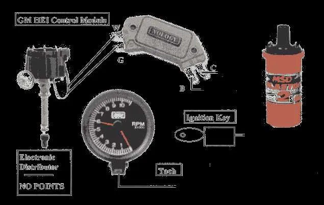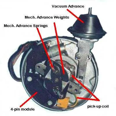
For reliable ignition performance, ensure correct connections between the control unit and the spark source. Begin by properly linking the power source to the coil, ensuring the correct voltage flows to trigger the ignition mechanism. Pay close attention to the proper grounding of the system, as an improper ground can lead to misfires or inefficient performance.
Next, connect the ignition module to the coil’s input. This step is crucial for precise timing control, ensuring that the spark is generated at the optimal moment for engine combustion. It’s recommended to double-check the polarity of the wiring to prevent damage to the components.
Ensure the signal wires are securely attached to the control system, allowing for seamless communication with the timing sensor. Each connection point must be tightly secured, and any loose wiring can cause delays in the ignition process or lead to engine performance issues.
Finally, don’t overlook the importance of choosing high-quality, durable materials for the wiring. Using subpar components can lead to overheating and degradation over time, potentially leaving you with frequent maintenance issues. Always opt for wires and connectors designed for high-voltage applications to maintain system reliability.
Proper Setup for High-Energy Ignition System
Connect the coil’s positive terminal to the ignition switch’s “on” or “run” position. This ensures the system gets power when the engine is running. The coil’s negative terminal should link to the control module or transistor that triggers the spark timing. It’s crucial to ensure a solid ground connection from the module to the engine block, as an unstable ground can lead to misfires.
For the signal from the module to the ignition coil, ensure the wire is securely connected to avoid voltage fluctuations. A typical setup uses a 12V supply for activation, with a low-resistance path through the coil to achieve consistent spark generation. A heavy-duty wire should be used to link the spark plugs for optimal performance and durability.
When adjusting, make sure the tachometer connection is stable to monitor the system’s RPM output. If you’re dealing with a multi-spark setup, ensuring each spark plug lead has equal resistance helps maintain uniform performance. Test each component individually to confirm that all connections are tight and corrosion-free.
Use shielded cables where interference from surrounding electrical components might affect spark timing. Proper wire routing avoids electromagnetic disturbances, ensuring precise ignition at each cylinder. Check all components periodically, especially under high heat conditions, as wiring integrity can degrade over time.
How to Identify the Correct Pinout for HEI System Connections

Start by locating the main connector on the ignition module. This will typically feature four to five pins depending on the system model. The pins serve specific functions, and understanding their layout is critical for proper installation.
The first pin is usually the 12V power input, which supplies current to the ignition coil. This pin should be connected directly to the battery or a suitable 12V source. Ensure the connection is secure and free of corrosion for consistent operation.
The second pin is often reserved for the ground connection. This must be securely attached to the engine block or chassis to ensure proper signal grounding. Without a proper ground, the system will fail to operate effectively.
Next, identify the pin linked to the tachometer output, commonly the third pin. This pin provides the RPM signal and must be routed to the tachometer or the vehicle’s computer system, depending on the application.
If your system features a fourth pin, it is usually connected to the bypass circuit, enabling the module to adjust timing under certain conditions. This pin must be carefully routed to the bypass switch or related component.
Lastly, the pin controlling the ignition coil signal is typically located in the center. This should be wired to the coil’s primary input, ensuring accurate firing of the spark plug at the right moment during the combustion cycle.
When connecting the pins, always verify the manufacturer’s specifications to ensure compatibility with your system. Using a multimeter can help confirm each connection’s functionality before final assembly. Miswiring can lead to engine misfires or complete failure to start.
Step-by-Step Guide to Connecting the Ignition Component to a Vehicle’s Electrical System

Ensure the ignition system is disconnected from the power source before beginning the installation. Start by identifying the key wires you’ll be working with: the 12V power supply, the signal from the ignition switch, and the ground wire.
- Power Connection
Connect the 12V supply wire to the designated terminal on the ignition system component. This provides the necessary voltage to activate the ignition process. Use a crimp connector to ensure a secure connection and avoid any loose fittings.
- Ignition Signal Input
Locate the ignition wire coming from the switch or control unit. This wire sends the signal to the ignition component when the engine is turned on. Attach this wire to the corresponding terminal, ensuring a tight and stable connection to avoid signal loss.
- Grounding the Unit
Ground the system by attaching the ground wire to a solid metal part of the vehicle’s frame or a dedicated grounding point. This ensures the circuit is completed and reduces electrical noise interference.
- Coil Connection
Connect the coil wire to the correct terminal on the ignition component. This link is essential for transferring energy from the coil to the spark plugs. Make sure the wire is insulated properly to prevent shorts.
- Testing and Adjustments
After making all necessary connections, recheck each wire for proper attachment. Power on the vehicle and test the system by starting the engine. If the engine fails to start or behaves erratically, verify that all connections are secure and the system is grounded properly.
Once all steps are complete, you should have a fully functional ignition system, ready for regular use. Regularly inspect the connections for wear and corrosion to ensure long-term performance.
Troubleshooting Common Electrical Issues in Ignition Systems
Check for faulty connections by inspecting the main power wire and ensuring a tight fit at the terminal. A loose connection can cause intermittent sparking or no ignition at all. Always clean the terminal and connector before reassembling.
Verify the coil’s integrity by testing it with a multimeter. The resistance should fall within manufacturer specifications. A reading that is too high or low can indicate an internal short or open, requiring coil replacement.
Grounding issues are another common culprit. Ensure that the grounding wire is properly secured to the engine block. A weak or poor ground connection can lead to erratic ignition performance, misfires, or complete failure.
Inspect the control module and associated wiring for any signs of damage, especially cracks or frays. Damaged wires can interrupt the signal and cause a misfire or no spark at all. If any wire is compromised, replace it promptly.
Check the capacitor for any signs of wear. If the ignition system exhibits weak spark or delayed timing, it could be an indication that the capacitor is failing. A quick test with an oscilloscope can confirm if it’s working properly.
Finally, corrosion around any electrical connectors should be cleaned thoroughly. Rust or debris can interfere with electrical continuity, leading to unreliable spark delivery or poor performance.