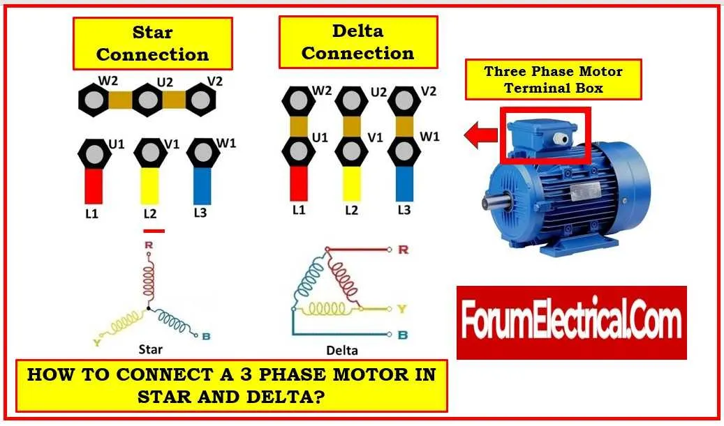
Connect L1 to terminal U1, L2 to V1, and L3 to W1 for standard clockwise rotation. For reverse direction, swap any two incoming conductors – for example, switch L1 with L3.
Delta setup: join U2 to V1, V2 to W1, and W2 to U1. Supply lines go to U1, V1, and W1. This method suits low-voltage grids, commonly 230V line-to-line.
Star connection: tie U2, V2, and W2 together and insulate the joint. Feed U1, V1, and W1 from the grid. This suits high-voltage systems like 400V or 690V depending on coil ratings.
Overload protection should be placed in each incoming path. Use thermal relays or electronic modules with adjustable trip current based on full load amps marked on the nameplate.
Measure insulation resistance between each terminal and ground before energizing. Values under 1 MΩ suggest damaged windings or moisture ingress – dry or replace the unit before use.
3 Phase Motor Wiring Diagram
Start by confirming the rated voltage and connection type on the nameplate: delta (Δ) or star (Y). This determines the terminal configuration.
- For a delta setup at 230V: connect terminals U1 to V2, V1 to W2, and W1 to U2. Apply supply lines to U1, V1, W1.
- For a star setup at 400V: link U2, V2, W2 together. Supply lines go to U1, V1, W1.
Include overload protection rated 115% of full load current. Place thermal relays on all incoming lines.
For reverse operation:
- Swap any two input conductors–L1 with L2, L2 with L3, or L3 with L1.
To integrate a contactor-based control scheme:
- Use a three-pole contactor rated for inductive load (AC-3 class).
- Install an auxiliary block for start/stop control using push buttons.
- Insert normally closed thermal relay contacts in series with the coil.
Ensure grounding at the frame with low impedance connection. Use color-coded conductors per IEC: brown (L1), black (L2), grey (L3), blue (neutral), green/yellow (earth).
How to Identify and Connect U, V, W Terminals on a 3 Phase Motor

Start by locating the terminal box cover and checking the nameplate for terminal designations. U, V, and W typically correspond to winding ends for a three-phase input. If markings are missing, use a digital multimeter set to resistance mode to find the three pairs with equal ohmic values–each pair belongs to one winding. Label the ends arbitrarily as U1–U2, V1–V2, and W1–W2 based on the resistance measurements.
For star (Y) configuration, connect U2, V2, and W2 together and apply L1, L2, and L3 to U1, V1, and W1 respectively. For delta (Δ), link U2 to V1, V2 to W1, and W2 to U1, then apply L1 to U1, L2 to V1, and L3 to W1. Always verify rotation direction by briefly powering the setup and watching shaft movement. If incorrect, swap any two incoming lines.
Use ferrules and torque tools to ensure secure connections. Confirm insulation resistance is above 1 MΩ before energizing. Avoid trial-and-error: incorrect sequencing may cause reverse rotation or uneven torque. Maintain clear labeling to simplify future troubleshooting.
Connecting a 3-Pole Electrical Machine to a Contactor and Thermal Protector

Start by identifying the three input leads from the power source and connect them to the line terminals of the contactor. Ensure tight and secure connections to prevent voltage drops or overheating. The output terminals of the contactor should then be linked to the three supply points of the rotating device.
Install the thermal overload relay immediately after the contactor’s output, wiring its input terminals to the device leads. The relay’s normally closed contacts must be wired in series with the coil circuit of the contactor to provide automatic disconnection during an overload.
Use conductors rated for at least 125% of the device’s full load current to handle startup surges safely. Ground the frame of the equipment following local electrical codes for protection against electrical faults.
Verify the control circuit operates at the specified control voltage. Connect the relay’s auxiliary contacts to the control line, ensuring proper polarity and secure fastening to avoid intermittent trips.
After completing the connections, test the system by energizing the contactor coil and checking for smooth engagement and disengagement. Measure the current through each line to confirm balanced load distribution and proper relay function.
Converting Star to Delta Connection in a 3-Lead Junction Box
To change from star to delta configuration inside the terminal enclosure, first disconnect all six leads. Identify the three line inputs and the six coil ends, typically labeled U1, V1, W1 and U2, V2, W2.
In delta setup, connect U1 to W2, V1 to U2, and W1 to V2, forming a closed loop of three connections. The incoming supply cables then attach to the junction points at U1, V1, and W1.
Ensure all contacts are secure and insulated to prevent shorts. Verify continuity between connected coil ends to confirm proper joining. Tighten terminal screws firmly to maintain stable contact under operational vibration.
After reconfiguration, check line-to-line resistance to ensure balanced loading across the windings. This conversion increases running current and torque but requires supply compatibility.