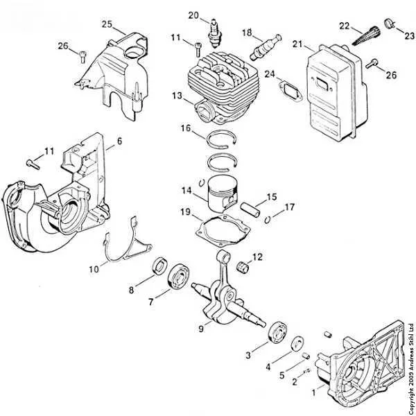
To ensure precise maintenance and efficient repairs, refer directly to the detailed schematic illustrating the assembly of the FS 55 model. This visual reference provides an exact layout of every element, from the fuel system to the cutting mechanism, enabling straightforward identification and ordering of necessary replacements.
Accurate part identification within this schematic eliminates guesswork, reducing downtime and preventing mismatched components. Each segment is labeled to correspond with official catalogs, facilitating compatibility checks and simplifying the servicing process.
Utilizing this explicit illustration helps maintain optimal performance by ensuring all units are correctly aligned and secured. Whether addressing carburetor adjustments or replacing ignition elements, the comprehensive blueprint serves as an indispensable tool for technicians and DIY enthusiasts alike.
FS 55 Component Layout
Identify key elements precisely: The ignition coil is positioned near the flywheel for optimal spark timing. The carburetor assembly is mounted adjacent to the engine block, ensuring efficient fuel delivery. The throttle trigger connects directly to the linkage system, controlling engine speed smoothly.
Use exploded views: This tool illustrates every segment, from the drive shaft to the cutting attachment, enabling clear visualization of how each unit fits together. Pay attention to the gasket sets and seals placed between joints to avoid leaks and maintain pressure.
Reference serial numbers: Each component is tagged with a unique identifier that corresponds to repair manuals and ordering catalogs, streamlining maintenance or replacement procedures. For example, the clutch drum labeled “C12” ensures correct matching during service.
Consult assembly order: Follow the stepwise layout starting from the base frame moving outward to auxiliary attachments. This prevents misalignment and ensures operational integrity. Bearings and washers are specified by diameter and thickness to guarantee fitment precision.
Locating and Identifying Key Components on the FS 55 Breakdown
Focus first on the engine assembly to find the ignition coil and spark plug, typically positioned near the top center of the schematic. The cutting attachment and its guard are clearly illustrated on the lower right section. Follow these steps for efficient identification:
- Locate the fuel system: Look for the fuel tank outline connected via lines to the carburetor, usually found on the left side of the layout.
- Identify the throttle mechanism: Trace the cable leading from the handle area to the carburetor linkage.
- Spot the air filter housing: Positioned adjacent to the carburetor, often shown as a rectangular or oval shape.
- Pinpoint the clutch and drive shaft: Central in the bottom half, connecting the motor to the cutting head.
- Check the starter assembly: Typically located on the upper left, depicted with recoil spring and pulley components.
Each component is numbered and linked to a reference list; cross-check these codes with the corresponding legend for precise part names and specifications. For complex assemblies, zoom in on exploded views to distinguish smaller fasteners and fittings without confusion.
- Use arrows and connection lines to understand the relationship between moving parts.
- Note the orientation indicators to avoid misinterpreting component positions.
- Refer to section callouts for subsystems such as the ignition circuit or fuel delivery.
Approach the schematic systematically from power source to output end for thorough comprehension and easier troubleshooting or ordering of replacements.
How to Use the FS 55 Component Blueprint for Accurate Replacement Orders
Identify the exact item number corresponding to the faulty element on the schematic before proceeding. Cross-reference this identifier with the official catalog code to avoid ordering errors. Pay close attention to the version and production year indicated in the illustration to ensure compatibility with your model.
Use the exploded view to verify the orientation and connection points of each unit, which helps confirm that the selected element fits precisely within the assembly. Note the quantity required per assembly to prevent under- or over-ordering.
When matching elements, rely on the part code rather than just the visual shape, as some components appear similar but differ in specifications or materials. Confirm the inclusion of necessary supplementary items like screws, washers, or seals, often listed adjacent to the primary component in the schematic.
Utilize the legend and numeric references to decode symbols indicating special features such as torque settings or installation instructions, which are crucial for correct application. Avoid assuming interchangeability; always check the detailed listing for each reference number to maintain system integrity.
Finally, maintain a record of the codes and descriptions during the selection process to streamline reordering and future maintenance tasks. This practice minimizes downtime and ensures consistent use of approved elements throughout the equipment’s lifecycle.
Troubleshooting Common Issues by Analyzing the FS 55 Component Layout
Start by inspecting the fuel system assembly; clogged fuel lines or a dirty filter often cause engine hesitation or failure to start. Replace or clean the fuel filter and ensure the tubing is free from cracks or blockages. Next, examine the ignition coil and spark plug position; misalignment or carbon buildup on the spark plug electrode frequently results in weak sparks and poor combustion.
Check the carburetor linkage and throttle mechanism for smooth operation–sticking parts can cause irregular engine speeds. Adjust the idle screw according to manufacturer specs to stabilize RPM fluctuations. The air intake housing should be clear of debris, as blockages reduce airflow and degrade performance. Verify that the recoil starter engages fully and retracts without delay to avoid startup issues.
Inspect the clutch assembly for wear or damage, especially the springs and friction surfaces; a slipping clutch can cause loss of power transmission. The cutting attachment mounting must be secure and balanced to prevent excessive vibration, which leads to premature component wear. Finally, confirm that all fasteners on the shaft and gearbox are tightened to spec to avoid mechanical failures during operation.