To properly connect a lighting circuit that allows control from more than two positions, you need to follow specific wiring techniques. This involves the use of special electrical components that are designed for multi-location operation. Understanding the correct installation steps will help ensure safety and functionality.
Begin by using electrical travelers for routing the current between switches. These wires connect two or more control points, facilitating the transmission of power through the circuit. The key to a seamless setup lies in the proper wiring of the traveler terminals at each control point.
Ensure that the common terminal is connected to the power supply at one of the switch points, while the remaining two terminals should be linked to the travelers. At each additional control point, connect the travelers and common terminals according to the same principle. The proper setup of these components allows for smooth operation of the circuit from any switch, without interrupting power flow.
By following these wiring principles and using the correct materials, you can set up a functional system to control lights from multiple locations. Pay close attention to the color codes and labeling to avoid wiring errors. Always check for continuity and functionality before finalizing the installation.
Wiring Circuit with Dual Control

To establish a dual control system for lighting, follow these precise steps:
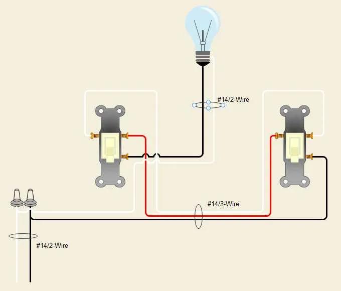
- Identify the components: You will need two controlling units (similar to standard single-pole devices), a light fixture, and the necessary wiring.
- Wire the first control unit: Connect the power supply to one terminal of the initial unit. The output terminal will go to the common terminal of the light fixture.
- Connect the travelers: Use two additional wires to link the second terminal of the first control unit to the corresponding terminals on the second control unit.
- Complete the circuit: Connect the second unit’s common terminal to the fixture’s light connection, ensuring the system is grounded properly.
- Verify the load and functionality: Test the installation by turning both controllers on and off to confirm the light can be activated from either point.
This setup allows for controlling a light from two separate locations, providing flexibility and efficiency. Ensure all connections are secure and follow local electrical codes for safety.
How to Wire a Circuit with Standard Connections
To properly connect a circuit with standard configurations, first, ensure the power is turned off. You will need two control units and a single light fixture. Start by connecting the power supply wire to the common terminal of the first control unit. This is typically the black wire from the electrical panel.
Next, connect a traveler wire from the first control unit to the second control unit. This wire should be inserted into one of the traveler terminals on both units. The same wire type (usually red or black) must be used for both terminals to maintain consistency.
At the second control unit, the traveler wire should be connected to the traveler terminal. The second unit also has a common terminal, which will connect to the light fixture. Attach the wire from the light to this terminal, ensuring the connection is secure.
Finally, connect the ground wire from the power source to the ground terminal on both control units and the light fixture. This ensures the circuit is properly grounded for safety. After all connections are made, double-check each connection before turning the power back on to test the functionality of the setup.
Troubleshooting Common Issues in Multi-way Lighting Circuits

If your multi-way circuit is malfunctioning, follow these steps to identify and resolve common problems:
1. Check for Incorrect Wiring: The most frequent issue is improper connections. Double-check that each terminal on the first and second devices is correctly wired to the corresponding terminals on the other unit. Ensure that the common terminal is connected to the power source and that the travelers are connected to the correct screws. Incorrect wiring will prevent the circuit from working properly.
2. Inspect for Loose Connections: Loose or corroded wire connections are a common cause of failure. Tighten all terminal screws securely, and ensure that no wires are frayed or exposed. Loose connections can cause intermittent lighting or complete failure of the system.
3. Test for Faulty Components: If the circuit still doesn’t function, the devices themselves may be faulty. Use a multimeter to check continuity across the terminals. A device that shows no continuity when it should be closed might need replacement.
4. Verify Power Supply: Ensure that the circuit is receiving power. A tripped circuit breaker or blown fuse can easily go unnoticed. Check the main panel to confirm there is power feeding into the circuit.
5. Ensure Proper Grounding: Grounding issues can also cause malfunctions. Confirm that all ground wires are connected to the metal boxes and the devices, ensuring proper grounding for safety and functionality.
6. Check for Interference: Sometimes, electrical interference can cause erratic operation. Ensure that no high-power appliances are interfering with the circuit’s normal operation. Switching off other devices in the area can help isolate this issue.
7. Inspect the Switch Mechanism: The internal mechanism inside the devices can wear out over time. If there is visible damage to the switch’s internals, or if it feels unusually loose or stiff, replacement may be necessary.
8. Review the Circuit’s Load Capacity: Ensure that the lighting load does not exceed the circuit’s capacity. An overloaded circuit will cause the components to malfunction or fail entirely. Verify the wattage of the bulbs and make sure they are within the recommended limits.
By systematically following these steps, you can identify the source of the issue and restore functionality to your lighting system. Always ensure you follow proper safety protocols when working with electrical components. If in doubt, contact a professional electrician for assistance.
Understanding the Role of Traveler Wires in Multi-Switch Systems
Traveler wires are essential for enabling remote control of a single load from two different locations. These conductors carry current between two control points, allowing the user to toggle the light or device from either end of the circuit. Properly connecting these wires ensures the system operates smoothly and without flickering or electrical failure.
Each traveler wire connects one switch to the other, forming a loop that allows the circuit to respond to inputs from either side. The wires should be connected to the correct terminals on both controlling devices, typically labeled as “common” and “traveler.” Any misconnection can prevent the system from functioning as intended, leading to a failure to turn the load on or off from one or both locations.
When wiring, it’s crucial to follow the correct color coding for travelers. Usually, these are marked as red and black wires, making it easier to differentiate them from the common or ground connections. Ensuring solid, secure connections is key to reducing the risk of shorts and enhancing the overall reliability of the installation.
If using a multi-pole configuration with more than two control points, additional traveler wires can be added. However, these must be appropriately routed and isolated to avoid crossing over other circuits or causing unintended interference.