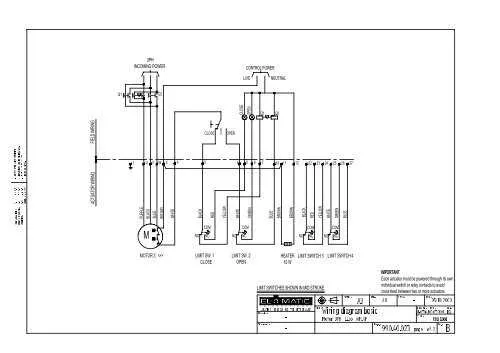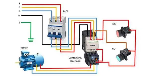
To achieve optimal performance and ensure safety when installing complex industrial machinery, it is crucial to understand the correct setup for connecting a motor to the power grid. Proper installation starts with accurately identifying the configuration of the terminals, the order of wires, and their respective connections to ensure smooth operation.
Follow the manufacturer’s guidelines when connecting the system, as incorrect connections can lead to equipment damage or operational inefficiency. For a typical setup, begin by identifying the input terminals on the control unit, then connect the power lines in the correct sequence, which will allow the machinery to operate at full capacity. Make sure to use color-coded cables or labeling systems to simplify maintenance and troubleshooting.
It is essential to double-check the voltage ratings of each connection. Using a multimeter before energizing the system will help confirm the integrity of the installation. Also, pay attention to the current rating and select appropriate protective devices like fuses or circuit breakers to prevent overloading and damage.
Ensure all components are securely fastened and that there is no risk of accidental short circuits or disconnections during operation. Correct insulation of the cables and proper grounding of the equipment are also critical to maintaining a safe working environment.
Proper Setup for Multi-Phase Induction Machine Connections
To ensure optimal performance, always verify the voltage and current ratings before connecting the system. Proper grounding is essential to prevent electrical hazards, and the correct sequence of connections will maintain the motor’s operational integrity. When dealing with a star or delta configuration, be sure to match the terminals according to the specific voltage rating. Typically, the U, V, W terminals correspond to the supply lines, and proper phase rotation is vital to prevent reverse operation.
For starters, always connect the primary leads to the main terminals, ensuring that the polarity is correct to avoid any malfunction. If using a contactor to control the system, a suitable overload relay should be installed to protect the unit from current surges. The system should be checked for proper insulation resistance and continuity between all connections before turning the machine on. Properly rated fuses or circuit breakers must be installed for overload and short-circuit protection, and regular inspections for wear and tear on wiring are recommended.
To guarantee the longevity of the unit, ensure that the voltage provided is within the operational limits of the equipment. Overvoltage or undervoltage can severely affect the performance and lifespan of the apparatus. When configuring the contactor for reversing functionality, the correct interlocking mechanism must be in place to prevent simultaneous engagement of both forward and reverse directions, which could lead to serious damage.
It is important to follow manufacturer instructions regarding the number of conductors required, the type of insulation needed, and the recommended torque values for the terminal screws. Miswiring or incorrect setups can lead to overheating, reduced efficiency, or permanent failure of the machine.
Understanding the Color Codes in Three-Phase Connections
In industrial setups, adhering to standardized color schemes for wiring ensures safety and ease of maintenance. The color codes used in a typical multi-line system are crucial for correctly identifying the conductors in the circuit. Typically, the first line is marked with black, the second with red, and the third with blue. The neutral conductor is usually white or gray, while the ground wire is green or green with a yellow stripe.
It’s vital to use these colors consistently to prevent errors during installation or troubleshooting. The black wire, for example, is always connected to the live terminal for the first line, ensuring proper current flow. Similarly, the red and blue lines follow the same pattern for the second and third lines, respectively, guaranteeing the correct phasing for the equipment.
Neutral wiring is often crucial in systems requiring a balanced load, and its identification by a white or gray conductor ensures it is properly linked to the return path. Ground conductors must always be correctly connected to avoid electrical hazards, and the use of green or yellow-green wires makes them easily identifiable for safety checks.
When working with these systems, always cross-check the wiring color codes with local regulations, as they may vary slightly depending on the region or country. Always ensure that each line is properly connected to avoid risks such as short circuits or equipment failure.
Connecting a Motor to a Star or Delta Configuration

When connecting a motor, the two most common configurations are star (Y) and delta (Δ). Both affect performance, starting torque, and operational efficiency. Here’s how to properly connect a unit to each configuration:
- Star Configuration: This setup is used for lower starting current and voltage. It reduces the motor’s input voltage to 1/√3 of the supply voltage.
- Delta Configuration: Ideal for maximum output power, this configuration connects the windings in a triangular form, providing full voltage to the motor.
Steps for Connecting to Star Configuration:
- Ensure the motor is capable of being connected in a star configuration (check the datasheet).
- Connect one end of each winding to a common point (neutral) and the other ends to the respective power supply lines.
- Confirm proper voltage matches before energizing the system.
Steps for Connecting to Delta Configuration:
- Verify that the unit is compatible with delta connection (check for terminal markings).
- Link the motor windings in a triangular loop, with each winding’s end connected to the beginning of the next winding.
- Ensure each line is connected to the motor’s corresponding terminal for the power supply.
Note: For high-efficiency operation, it’s common to use a star connection for startup and then switch to delta once the unit reaches a certain speed. This is known as the star-delta starting method.
Troubleshooting Common Wiring Issues in Motors
Start by verifying the power supply. Check if all connections are secure and that there is no voltage drop. Measure the input voltage at the terminal block to ensure consistency with manufacturer specifications. Any significant deviation could indicate issues with the power source or incoming lines.
Next, inspect the connection sequence for each wire. Incorrect phasing can cause the system to run in reverse or not at all. Use a phase rotation meter to confirm the correct order of phases. If there’s a mismatch, swap any two wires to correct the rotation direction.
Loose connections can cause intermittent failures and overheating. Tighten all terminal screws and check for any signs of wear or corrosion on connectors. Additionally, ensure that wire gauges match the specifications for the current load to avoid excessive heating or failure.
If the device fails to start, ensure the contactor is functioning correctly. A stuck or faulty contactor can prevent current flow. Test the relay and control circuit for proper operation and replace any damaged components.
For consistent performance, regularly inspect the insulation resistance. A drop in insulation resistance can lead to shorts or ground faults. Use a megohmmeter to measure the resistance between windings and ground. Values below the manufacturer’s recommended range should be addressed immediately.
Grounding issues can lead to severe faults. Ensure that all components are properly grounded and that the ground connection is secure. An improper or missing ground can cause erratic behavior or even damage sensitive electronics.
Finally, check the overload protection settings. Incorrect calibration can lead to unnecessary tripping or failure to trip during an overload condition. Adjust the settings to match the motor’s operating requirements and ensure the protection device is in working order.