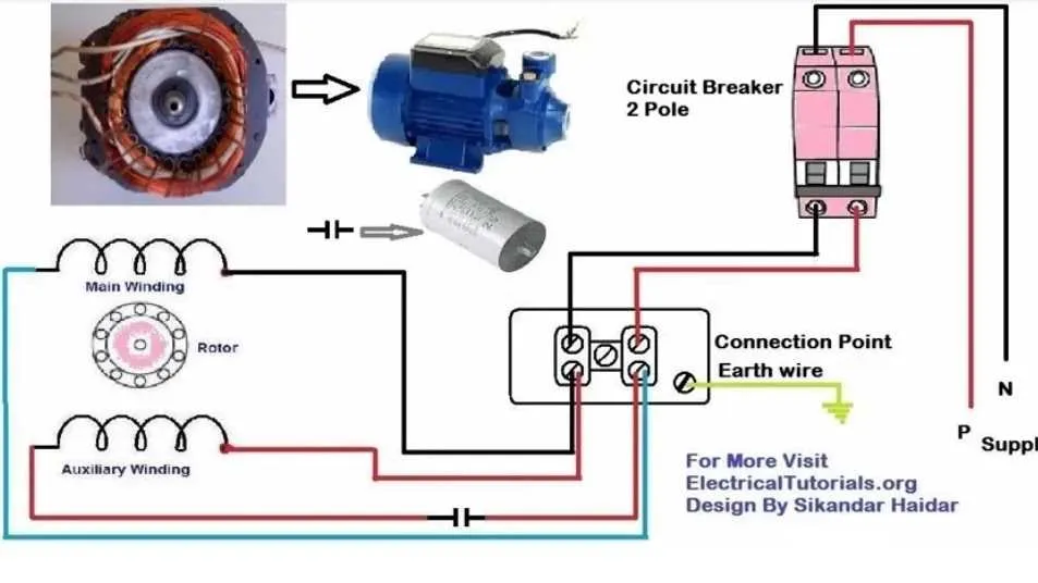
Always start by identifying the terminal markings: most compact electromechanical units use labels such as U1, U2, Z1, Z2, or simply 1, 2, 3. For setups involving an auxiliary coil, these labels help distinguish the primary winding from the secondary one. Use a multimeter to verify resistance–higher resistance typically indicates the secondary circuit.
Capacitor-based arrangements require accurate placement of the component between the primary and auxiliary paths. For split-start models, the capacitor connects in series with the auxiliary path and is removed after startup, usually by a centrifugal switch or relay. For permanent-split types, the component remains in the circuit during continuous use.
Line voltage (typically 220–240V AC) is applied to the main and assistive routes. One wire from the power source connects directly to the common terminal, while the other wire splits–one side goes to the main path, the other to the secondary through the capacitor.
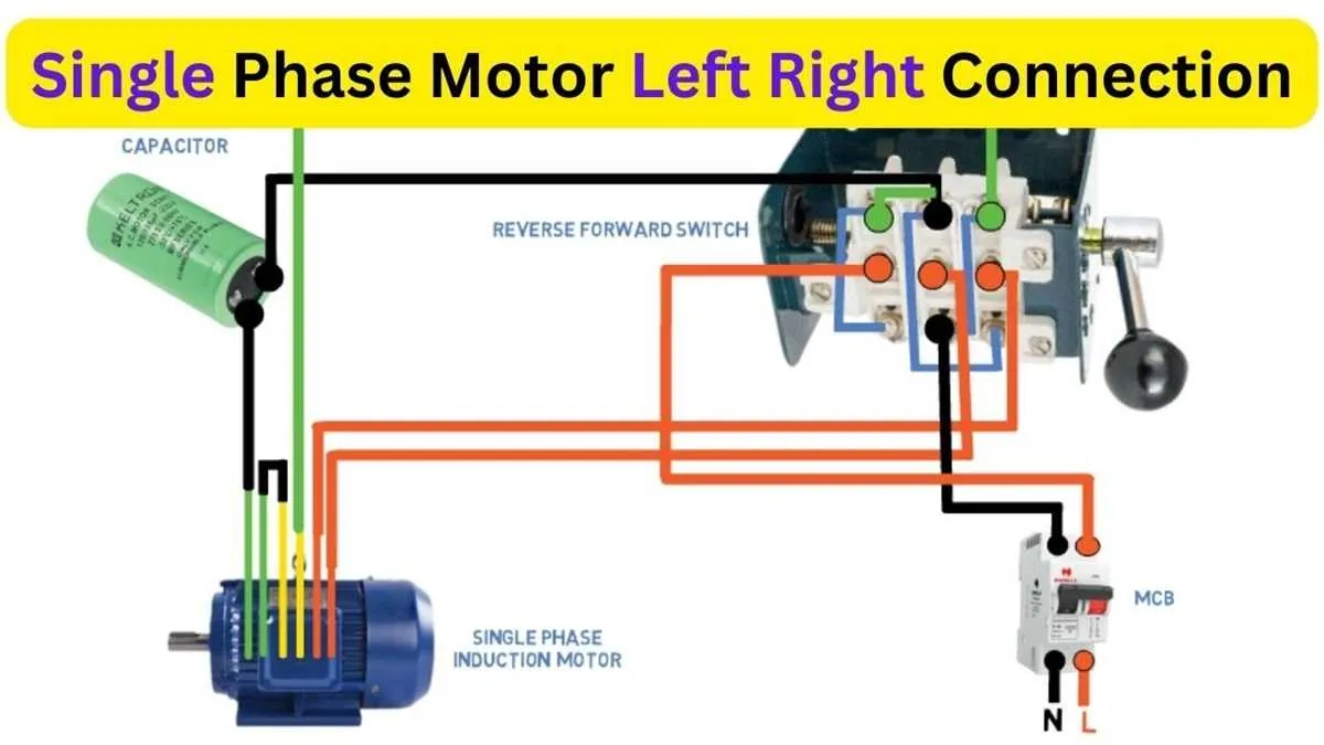
For units with directional capabilities, swapping the auxiliary ends reverses rotation. Always isolate power before making changes. Miswiring may damage internal elements or cause safety risks.
Use proper wire gauges, secure all terminals with tightening torque per manufacturer’s spec, and confirm operation with no-load testing before full deployment.
Wiring Layout for Single-Line AC Drive
Start by identifying the live (L) and neutral (N) wires from the power source. Attach the live wire to terminal L1 and the neutral to terminal N of the drive unit. Use a capacitor rated between 20µF to 40µF, connecting it between the auxiliary and primary windings. For clockwise spin, link the capacitor between the start terminal and one of the supply inputs, typically L1. To reverse direction, shift the capacitor to the other winding leg.
Ensure the ground wire is firmly attached to the chassis earth terminal. For thermal protection, integrate a bimetallic breaker or thermistor in series with the live input. Confirm all terminals are tightened to avoid arcing or overheating. Use 1.5 mm² copper wire for units under 1.5kW and upgrade to 2.5 mm² for higher ratings.
Always isolate supply power before wiring. Verify voltage compatibility, typically 220–240V AC for residential systems. Cross-check all labels and color codes: brown for live, blue for neutral, green-yellow for earth. Avoid twisting conductors or sharing grounds with unrelated devices to reduce EMI and ensure consistent operation.
Wiring a Single Unit with Capacitor Start
Always begin by identifying the start and run windings using a multimeter. The start coil typically shows higher resistance. Follow these steps for reliable assembly:
- Disconnect power supply before any manipulation.
- Locate four terminals: two for the working coil, two for auxiliary.
- Connect the live wire to one side of the active winding.
- Link the neutral line to the other side of the same coil.
- Install the capacitor in series with the assist winding.
- Bridge one end of the capacitor to the live input.
- Join the other capacitor end to one terminal of the auxiliary coil.
- Connect the remaining auxiliary terminal to the neutral path.
Use an electrolytic or oil-filled capacitor rated for at least 250V AC. Choose capacitance based on the device’s specifications, typically between 40μF–100μF for 1–2 HP units.
Secure all terminals using ring lugs and insulate exposed connections with heat shrink tubing. Confirm rotation direction; reverse by swapping auxiliary ends if needed. Ensure proper thermal protection before activating.
How to Reverse Rotation Direction in a Single Phase Motor
Swap the start winding leads: To reverse the turning direction, identify the two wires connected to the auxiliary coil. These are typically labeled as start or run start. Exchange these two conductors while keeping the main coil terminals unchanged.
Check the centrifugal switch or capacitor wiring: Ensure that the switching mechanism or phase-shifting element remains correctly oriented after the swap. Reversing these inadvertently can prevent proper operation or cause damage.
Use color codes or markings: Common wire pairs include black and red or blue and yellow for auxiliary circuits. Follow manufacturer-specific wiring conventions to avoid miswiring.
Never interchange main winding wires: Reversing the active coil lines has no effect on rotation and may lead to overheating or malfunction.
Power down and discharge capacitors before adjustments. Use a multimeter to verify continuity and correct layout before applying voltage again.
Integrating Overload Protection in a Single-Winding Electrical Machine Circuit

Install the overload relay directly in series with the supply line feeding the stator winding. This device must be rated according to the rated current of the appliance, typically 115% to 125% of the full-load current. Connect the relay coil so that it monitors the current flow continuously, allowing it to trip the circuit breaker or contactor coil in case of excessive current draw.
Use thermal or electronic overload relays compatible with the control circuit voltage, ensuring reliable disconnection during overheating or locked-rotor conditions. Place the relay between the main power source and the start capacitor or centrifugal switch if present, to protect both windings and auxiliary components.
Verify that the overload device is adjustable to match the locked-rotor and running current ratings specified by the equipment manufacturer. Employ short-circuit protection upstream, such as fuses or miniature circuit breakers, to complement the overload relay function and prevent wiring damage.
Ensure wiring terminals are tightly secured, and test the relay trip function regularly under simulated fault conditions to maintain safety and prolong operational lifespan. Proper installation prevents damage from overheating caused by mechanical jams, stalled rotation, or electrical faults.